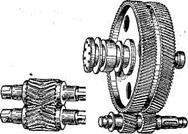
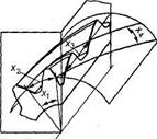
Helical are called wheels in which the theoretical pitch line of the tooth is part of a helical line of constant pitch (the theoretical pitch line is the line of intersection of the side surface of the tooth with the pitch cylindrical surface). The tooth line of helical gears may have right And left direction of the helix. The angle of inclination of the tooth line is designated β (Fig. 1.58).
Rice. 1.58. Helical gear with parallel axes
Helical gear with parallel axes has opposite direction of teeth driving and driven wheels and belongs to the category of cylindrical gears, since the initial surfaces of such gear wheels represent lateral surface cylinders A gear with helical wheels, the axes of which are crossed, has the same direction of the teeth of both wheels and is called helical gear(see Fig. 1.52, And), which belongs to the category of hyperboloid gears, since the initial surfaces of such gears are parts of a single-cavity hyperboloid of revolution; The dividing surfaces of these wheels are cylindrical.
In helical gears, the contact lines are located obliquely relative to the tooth line (Fig. 1.58), therefore, unlike straight ones, helical teeth do not engage immediately along the entire length, but gradually, which ensures smooth engagement and a significant reduction in dynamic loads and noise during operation transfers. Therefore, helical gears, compared to spur gears, allow significantly higher maximum peripheral wheel speeds.
The overlap angle of the helical gear consists of the end angle and the axial overlap angle, therefore, the overlap coefficient ε γ of the helical gear equal to the sum coefficients of end ε α and axial ε β overlap:
ε γ = ε α + ε β > 2,
so u Helical gears do not have a single-pair gearing period.
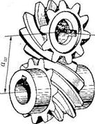
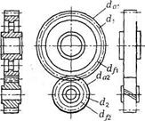
Helical gears are processed with the same gear-cutting tools as spur gears, therefore standard wheel parameters are specified in the section normal to the tooth(Fig. 1.59, A). Normal module Tn= pn/π,where Rn– normal pitch measured along the pitch surface. In addition to the normal module, helical gears include: circumferential module m t= p t/π,where p t– circumferential pitch measured along an arc pitch circle in the end section; axis module t x = p x/π, where p x – axial pitch measured along the generatrix of the dividing cylinder.
Because p t= p n/cosβ, then m t= m n/cosβ.
The dimensions of the teeth of a helical gear are determined by the normal module, i.e.
h = h a + h f = m n + 1,25m n = 2,25Tn,
and the diameter of the pitch circle of the wheel according to the circumferential module
d = m t z= m n z/cos β.
The dimensions of helical gears and the center-to-axle transmission distance are determined using the following formulas:
tooth tip diameter
d a= d+ 2h a= d+ 2m n;
dimple diameter
d f= d– 2h f= d– 2,5Tn;
center distance
A= m t(z 1 + z 2)/2 = m n(z 1 + z 2)/(2cosβ).
Axial overlap coefficient of helical gear
ε β = b/p x,
Where: b– crown width; p x – axial step.
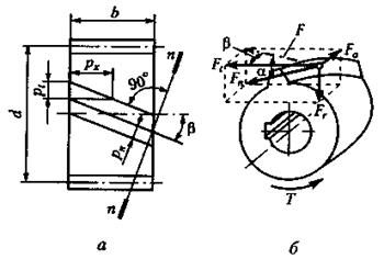
Rice. 1.59. Standard parameters of helical gear
It is easy to show that Ifε β – an integer, then the total length of the contact lines will remain constant all the time,
l Σ = bεα/cosβ.
Unlike helical gears in helical gears (see Fig. 1.52, And)not linear, but point contact occurs between the teeth, which significantly increases contact stresses and reduces the load capacity of the transmission. In addition, in a helical gear transmission, the relative sliding of the teeth reaches a significant value, which significantly reduces its efficiency, creates a tendency to jam and causes rapid wear of the teeth. Given these disadvantages, helical gears should not be used as power transmissions.
A prerequisite for screw gear train – equality of normal modules. The inclination angles of the tooth line of the driving and driven wheels may be different, and the crossing angle of the axes may not be equal to 90°.
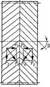
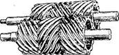
A cylindrical gear wheel, the width of which consists of sections with right and left teeth, is called a chevron gear (see Fig. 1.52, V). The part of the crown with teeth of the same direction is called half-chevron. For technological reasons, chevron wheels are made of two types (Fig. 1.60): with a track in the middle of the wheel ( A) and without track ( b). In a chevron wheel, axial forces Fa on half-chevrons directed in opposite directions, are mutually balanced inside the wheel and on the shafts, and the shaft supports are not transferred. Therefore, chevron wheels The angle of inclination of the teeth is taken within the range β = 25...40°, as a result of which the strength of the teeth, the smooth operation of the transmission and its load capacity increase. Chevron wheels are used in powerful high-speed closed transmissions. The disadvantage of chevron wheels is the high labor intensity and cost of production. Geometric, kinematic and strength calculations Chevron and helical gears are similar.
It is easy to show that If e r – integer, then the total length of the conthe clock lines will remain constant all the time, which is beneficial for the operation of the transmission, since the load on the teeth during the meshing process will remain constant, and noise and dynamic loads will decrease. The total length of the contact lines in this case is equal to
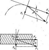
Strength normal pressure F n in the engagement of helical gears can be decomposed into three mutually perpendicular components (Fig. 7.10.6): circumferential force tv, radial force. R g and axial force Fa, equal:
F t =2T/d; F r =F c tg a/cosp; F a = F,tg|3,
Where T- transmitted torque; a is the engagement angle.
The presence of axial force is a significant disadvantage of helical gears. To avoid large axial forces in a helical gear, the angle of inclination of the tooth line is limited to p = 8... 20°, despite the fact that with increasing p, the strength of the teeth, the smoothness of the gear, and its load capacity increase.
In modern gears, helical wheels have an advantagenew distribution.
Unlike helical gears in helical gears (see Fig. 7.1, And) Not linear, but point contact occurs between the teeth, which significantly increases contact stresses and reduces the load capacity of the transmission. In addition, in a helical gear transmission, the relative sliding of the teeth reaches a significant value, which significantly reduces its efficiency, creates a tendency to jam and causes rapid wear of the teeth. Given these disadvantages, helical gears should not be used aspower transmission.
Mandatory condition for helical gear drive– equalitynormal modules. The inclination angles of the tooth line of the driving and driven wheels may be different, and the crossing angle of the axes may not be equal to 90°.
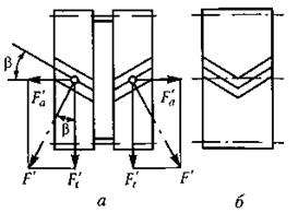
Rice. 1.60. Types of chevron wheels
Equivalent wheels. The strength of a helical gear tooth is determined by its shape and dimensions in the normal section and the length of the tooth. In order to unify the methodology for calculating the strength of straight and oblique teeth, the concept of an equivalent wheel was introduced. An equivalent spur gear is a wheel whose dimensions and shape of teeth approximately coincide with the dimensions and shape of a helical gear tooth in a normal section. Figure 1.61 shows a helical gear intersected by a plane pp;the normal section of the cylindrical pitch surface of this wheel is an ellipse with axle shafts e= d/(2cosβ) and с = d/ 2, Where d– diameter of the pitch circle. As is known from analytical geometry, the maximum radius of curvature of an ellipse
ρ v= e 2 /c= d/(2cos 2 β).
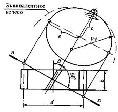
Rice. 1.61. Helical and equivalent spur gears
This radius of curvature is taken as the radius of the pitch cylinder of the equivalent wheel, then its diameter
d v= d/cos 2 β.
Substituting into this expression d v= m n z v And d= m n z/cosβ, we obtain a formula for determining the number of teeth of an equivalent spur gear (equivalent number of teeth)
z v= z/ cos 2 β.
Options d v And z v equivalent gears increase with increasing angle β, which is one of the reasons for the increase in the load capacity of helical gears compared to spur and makes it possible, with the same load, to have a transmission with smaller overall dimensions.
Chevron cylindrical gears. The chevron wheel is a double helical wheel made as one piece, see fig. 1, c. Due to the different directions of the teeth on the half-chevrons, the axial forces Fa2 are mutually balanced on the wheel and are not transmitted to the bearings (Fig. 16. This circumstance makes it possible to adopt a tooth angle of 25 40 for chevron wheels, which increases the strength of the teeth and the smoothness of the transmission.
Chevron gears are made with a track in the middle of the wheel for exit cutting tool hob cutter in Fig. 16 or without a track are cut with a cutter or comb with a special sharpening, see fig. 1, c. Chevron wheels without a track are cut on special low-productivity and expensive machines, so they are used less often than wheels with a track.
The width of the path is 10 15 m. A chevron tooth requires a strictly defined axial position of the gear relative to the wheel, so the pairs are mounted in bearings that allow axial play of the shaft. The disadvantage of chevron wheels is the high cost of their manufacture. Used in powerful high-speed closed gears. The geometric and strength calculations of a chevron gear are similar to those of a helical gear. For a chevron transmission, the wheel rim width coefficient is 0.40.8. With strict parallelism of the teeth and axes O2O2 and O1O1, straight teeth engage along the entire length B in Fig. 17, a If a wheel of width B, having straight teeth, is cut into a number of thin wheels 1, 2, 3, 4, 5 Fig. 17, b and rotate each of them on the axis relative to the previous one at a certain angle so that the tooth moves by arc s, then you get a wheel with a stepped tooth. When the wheels rotate, sections 1 1, 2 2, 3 3, etc. will engage in succession. In the same sequence, they will disengage.
Taking endlessly big number infinitely thin wheels, we get an oblique helical tooth inclined to the axis of rotation at an angle in Fig. 17, c. Oblique teeth work more smoothly compared to straight teeth, since the more teeth with the same wheel width B. A significant disadvantage of helical wheels is the presence of an axial force Ros, which tends to move the wheels along the shaft axis. From fig. 17, c it is clear that the larger the angle b, the greater the axial force Roc will be at the same circumferential force P0cr. On fig. 17, c shows the direction of pressure of the gear tooth on the wheel tooth. To eliminate axial load on the supports, two helical gears with teeth inclined in opposite directions are installed on the shaft.
It should be borne in mind that if the longitudinal installation of the wheels on the shaft is inaccurate, it may turn out that only one pair of teeth from two mating pairs of wheels will be in contact, for example the left one, as shown in Fig. 18 As a rule, one of the shafts is made self-aligning relative to the other.
The axial force Ros tends to move the shaft together with the wheel attached to it to the left. To distribute the circumferential force Rocr equally on both wheels, it is necessary to provide a longitudinal so-called mounting gap e between the support and the side of the shaft. After the gear and shaft shift to the left under the influence of the force Ros, the pressure on both halves of the wheel and gear is distributed equally. 1.8
End of work -
This topic belongs to:
Helical gears
Gear parameters are assigned index 1, wheel parameters are assigned index 2. Gear drives are the most common type mechanical gears, because... Advantages. 1. High reliability of operation in a wide range of loads and... Classification.
If you need additional material on this topic, or you did not find what you were looking for, we recommend using the search in our database of works:
What will we do with the received material:
If this material turned out to be useful for you, you can save it to your page on social networks:
| tweet |
All topics in this section:
Fundamentals of Gear Theory
Fundamentals of gear theory. N The tooth profiles of a pair of wheels must be conjugate, i.e., a given tooth profile of one wheel must correspond to a very specific tooth profile of the other
Manufacturing of gears
Manufacturing of gears. Gear blanks are produced by casting, die forging or free forging depending on the material, shape and dimensions. Wheel teeth are made by rolling
Gear materials
Gear materials. The choice of gear material depends on the purpose of the gear and its operating conditions. Steel, cast iron and plastic are used as wheel materials. Become. Main
Types of tooth destruction and gear performance criteria
Types of tooth destruction and performance criteria of gears. During operation, the teeth are subject to the forces of transmitted load and frictional forces. For each tooth, the stresses vary according to
General information
General information. Cylindrical wheels, in which the teeth are located along helical lines on the index cylinder, are called helical gears and see fig. 1, b. Unlike straight tooth to helical
Equivalent wheel
Equivalent wheel. A-A As mentioned above, the profile of an oblique tooth in a normal section A A Fig. 14 corresponds to the original contour of the tool rack and, therefore, coincides with the profile of the
Meshing forces
Meshing forces. In a helical gear, the normal force Fn makes an angle in with the end of the wheel (Fig. 15. Decomposing Fn into components, we obtain the radial force where Ft 2T2 d2 circumferential force axial force Pr
Calculation of contact strength
Calculation of contact strength. Due to the inclined arrangement of the teeth, several pairs of teeth are simultaneously located in the helical gearing, which reduces the load on one tooth, increasing its strength
Bending calculation
Bending calculation. Similar to the calculation of a spur gear, the conditions for the bending strength of the teeth of the gear and wheel of a helical gear where YF is the tooth shape coefficient, are selected according to the equivalent number of teeth
Gear transmissions with meshing M. L. Novikova
Gear transmissions with M. L. Novikova gearing. Involute gearing, common in modern mechanical engineering, is linear, since the contact of the teeth occurs along the line
3.49. Helical gears, like spur gears, are designed to transmit torque between parallel shafts(Fig. 3.36). In helical gears, the axes of the teeth are located not along the generatrix of the dividing cylinder, but along a helical line making an angle β with the generatrix (Fig. 3.44). The angle of inclination of the teeth p is taken equal to 8÷18°, it is the same for both wheels, but on one of the mating wheels the teeth are inclined to the right, and on the other to the left.
Rice. 3.36. Cylindrical helical gear
The gear ratio for one pair of wheels can be and ≤ 12. In spur gears, the contact line is parallel to the axis, and in helical gears it is located diagonally on the surface of the tooth (contact in straight gears is carried out along the entire length of the tooth, and in helical gears, first at a point it increases to a straight line, “diagonally” gripping the tooth, and gradually decreases to the point).
Advantages of helical gears compared to spur gears: reduction of noise during operation; smaller overall dimensions; high smoothness of engagement; high load capacity; significantly lower additional dynamic loads.
Due to the inclination of the tooth in the engagement of the helical gear, an axial force appears.
The direction of the axial force depends on the direction of rotation of the wheel (Fig. 3.37), the direction of the helix of the tooth, and also on whether the wheel is driving or driven. The axial force additionally loads the shafts and supports, which is a disadvantage of helical gears.
Rice. 3.37. Forces in helical spur gear
3.50. Chevron gears are a type of helical gear.(Fig. 3.38).
a) b)
Rice. 3.38. Chevron gear
A cylindrical gear wheel, the width of which consists of sections with right and left teeth (Fig. 3.38, A), called a chevron wheel. Part of the crown gear wheel, within which the lines of the teeth have one direction, is called a half-chevron. There are chevron wheels with a rigid angle (Fig. 3.38, b), designed for the exit of the cutting tool when cutting teeth. Chevron gears have all the advantages of helical gears, and the axial forces (Fig. 3.39) are oppositely directed and are not transmitted to the bearing.
Rice. 3.39. Efforts in engagement of chevron gears
These gears allow a large tooth angle (β = 25 ÷ 40°). Due to the complexity of manufacturing, herringbone gears are used less frequently than helical gears, that is, in cases where it is necessary to transmit greater power and high speed, and axial loads are undesirable.
Will an axial force occur in a transmission consisting of gears (Fig. 3.40)? How is this gear different from a helical gear?
3.51. Helical and chevron gears, unlike spur gears, have two pitches and two modules: in a normal section (see Fig. 3.44) along the pitch circle - normal pitch r p, in the end plane - end step p t . From the condition that the linking modulus is equal to the step divided by the number π, we have t p = p 1 /π; t t = p t /p.
For helical and chevron wheels, normal modulus values t n are standardized, since the profile of an oblique tooth in a normal section corresponds to the original contour of the tool rack and, therefore, T= t p(helical and chevron wheels are cut in the same way and with the same tool as straight teeth). Normal module t p is the starting point for geometric calculations.
Let us determine the relationship between normal and axial pitch and modulus through the angle of inclination of the teeth.
If we divide the left and right sides by l, we get
m n = m t cosβ; m t= m n /cosβ.
3.52. Geometric parameters cylindrical helical and chevron gears with an involute tooth profile will be calculated using the formulas given in table. 3.13. By end module t t calculate the pitch (initial) diameters, and before t p- all other gear sizes.
Table 3.13. Geometric parameters of a cylindrical helical gear
| Parameter, designation | Calculation formulas | |
| Normal module T" | | |
| End (circumferential module) t t | | |
| Tooth tip diameter d a | | |
| Pitch diameter d | | |
| Tooth root diameter d f | ||
| Step is normal р n | ||
| End pitch (circumferential) p t | | |
| Circumferential thickness of teeth S t | ||
| Tooth Gullet Width e t | ||
| Parameter, designation | Calculation formulas | |
| Tooth height h | h= 2.25mn | |
| Tooth head height h a | h a = m n | |
| Tooth stem height h f | h f .=l.25m n | |
| Radial clearance with | c = 0.25m n | |
| Center distance a ω |
|
|
| Tooth length b | |
|
| Crown width b ω |
District force F t = P/v. An axial force acts on an oblique tooth F a = F t tgα(see Fig. 3.37), radial (expansion) force F r = F t tga/cosβ.
Determine t p and m t if known pitch diameter and center distance.
3.53. IN
in a helical gear, the force F acting on a helical gear tooth
(cm. rice. 3.44), directed normal to the tooth profile, i.e. along the engagement line
angle of the equivalent spur gear, and makes an angle a with the tangent to
ellipse.
We will decompose this force into two components: the circumferential force on the equivalent wheel Ft and radial (spacer) force on this wheel Fr.
If, in turn, force F) expand in two directions, we get the following forces: F,- circumferential force, Fa- axial.
3.54.
For a chevron gear, the circumferential force F 1 and races
porn F r determined by the same formulas as for helical gears,
i.e. F t = P/v, F r = F t tgα/cosβ. In a chevron gear, the axial force F a = 0(cm.
rice. 3.39).
Why in a chevron gear (see Fig. 3.38) is the axial force zero?
3.55. Helical gear(a type of helical) consists of two helical cylindrical wheels (Fig. 3.42). However, unlike helical cylindrical gears with parallel shafts, contact between the teeth here occurs at a point and at significant sliding speeds. Therefore, under significant loads, helical gears cannot operate satisfactorily.
According to fig. 3.42 determine how the shaft axes of the screw drive are located.
Rice. 3.41. Helical gear
3.56. Answer the questions on test card 3.8.
| Test card 3.8 | ||
| Question | Answers | Code |
| Show in Fig. 3.42 normal tooth pitch R" | X 1 X 2 X 3 X 4 Not shown in the picture | |
| What are the limits of the tooth angle (p) for a helical gear transmission? | 8 ÷ 18° 25 ÷ 45° 20° 90° | |
| Which module is taken as standard when calculating helical gears? | T n t t Both | |
| Specify the formula for calculation gear ratio helical gear, if the diameters shown in Fig. 3.43 | da/da da 2 /da x d/d 2 d 2 /d\ | |
| What module is used to calculate the pitch size in a helical gear? | T n m y On both |
Rice. 3.42
Geometric parameters. In helical gears, the teeth are not located along the generatrix of the dividing cylinder, but make a certain angle /? (Fig. 8.23, where a is a helical gear; b is a chevron gear, and Fig. 8.24). The wheel axles remain parallel. To cut oblique teeth, use a tool with the same initial contour as for cutting straight teeth. Therefore, the profile of an oblique tooth in the normal section n - n coincides with the profile of a straight tooth. The module in this section must also be standard (see Table 8.1).
In the end section / - t helical tooth parameters vary depending on the angle /?: circumferential pitch pt=pn/cosfi, Circumferential module mt=mn/cos/?, pitch diameter d = mtz= Th^/ Cos/?.
The indices pi / are assigned to the parameters in the normal and end sections, respectively.
The strength of a tooth is determined by its size and shape in a normal section.The shape of an oblique tooth in a normal section is usually determined through the parameters of an equivalent spur gear(Fig. 8.25).
The cross section of the oblique wheel, normal to the tooth, forms an ellipse with axle shafts With= g and e=g/ Cos/?, where r=d/2. The engagement involves teeth located
On the minor axis of the ellipse, since the second wheel is at a distance C = D/2. Radius of curvature of the ellipse on the minor axis (see ellipse geometry)
Rv = E2 / C = R/ Cos2 /?.
In accordance with this, the shape of an oblique tooth in a normal section is determined by an equivalent spur gear, the diameter of which
dv= D/ Cos2 P (8.21)
And number of teeth
Zv= sTstp =DJ{ Mn Cos2 /?)= Mtz/(Mt Cos3 /?),
Zv=z/cos30. (8.22)
Example. AtP= 20°,<4 = 1,134 Zv= 1,2 Z.
Increasing equivalent parameters(dv And Zv) with increasing anglefiis one of the reasons for increasing the strength of helical gears. Due to the inclination of the teeth, a larger wheel is obtained, or the dimensions of the gear are reduced under the same load. It is shown below that helical gears have other advantages compared to spur gears: multiple gearing pairs, noise reduction, etc. Therefore In modern gears, helical gears have become prevalent.
Multiple pairing and smoothness of engagement. Unlike straight teeth, oblique teeth do not engage immediately along their entire length, but gradually. The engagement here extends in the direction away from the points 1 to the points 2 (See Fig. 8.24). The location of the contact lines in the helical gear field is shown in Fig. 8.26, a, b* (cf. Fig. 8.5 - spur gear). When the wheels rotate, the contact lines move in the engagement field in the direction shown by the arrow. At the considered moment in time, three pairs of teeth 7 are in mesh, 2 And 3. At the same time, the couple 2 hooks along the entire length
♦More precisely, the contact lines are located not at an angle /?, but at an angleft. The difference between these angles is small, and its influence on al does not exceed 2%. Therefore, hereinafter we accept
Teeth, and pairs 7 and 5 - only partially. At the next moment of time, pair 3 disengages and is in position 5". However, two pairs still remain in engagement 2
AndD. Unlike a spur gear, an oblique tooth engagement does not have a single-pair engagement zone.In a spur gear, the load is transferred instantly from two teeth to one or from one to two. This phenomenon is accompanied by shocks and noise.In helical gears, the teeth are loaded gradually as they enter the meshing field, and there are always at least two pairs in mesh. The smoothness of the helical gearing significantly reduces noise and additional dynamic loads.
The noted advantage of helical gearing becomes especially significant in high-speed gears, since dynamic loads increase in proportion to the square of the speed.
In helical gearing, the load is distributed over the entire total length of contact lines 7, 2, 5. The specific load decreases with increasing total length of contact lines /L. Using Fig. 8.26 it is easy to establish that for ea equal to an integer,
K = BwEa/ Cos/?
And /L does not change during movement, since the decrease in lines 3 always corresponds to an equal increase in line 7. It is also constant for any ea, but for e^ equal to an integer. If the noted conditions are not met, then k changes periodically, and formula (8.24) will determine the average value, which is taken as the calculated one.
In accordance with formula (8.24), /z increases with increasing /?, which is beneficial. However, to avoid large axial forces in engagement
(see below) it is recommended to take /?=8...20°. For chevron wheels, /? up to 30° and even up to 40°.
On the lateral surface of an oblique tooth, the contact line is located at a certain angle to (Fig. 8.27, a). Angle X increases as /? increases. The load is distributed unevenly along the contact line. Its maximum is at the midline of the tooth, since when engaged by the midpoints, the teeth have maximum total rigidity.
When the tooth moves in the engagement plane, the contact line moves in the direction from 7 to 5 (Fig. 8.27, b). In this case, position 7, in which the corner of the tooth breaks off, can be dangerous for strength. A fatigue crack forms at the root of the tooth at the point of stress concentration and then propagates at a certain angle c. The probability of an oblique fracture is reflected in the strength of the teeth in terms of bending stresses, and the load concentration Q- on the strength of contact stresses.
Associated with the inclined position of the contact line the feasibility of manufacturing a helical gear from a material that is much more durable (highly hard) than that of the wheel. This is explained as follows. The legs of the teeth have less resistance to chipping than the heads, since they have an unfavorable combination of the sliding direction and rolling of the teeth (see Fig. 8.6 and 8.8). Consequently, the leg of the gear tooth working with the gear tooth head will begin to chip first. In this case, due to the inclination of the contact line, the load (fully or partially) is transferred to the head of the gear tooth, which works with the pinion of the gear tooth. The weak leg of the wheel tooth is relieved and chipping stops. The additional load on the gear tooth leg is not dangerous, since it is made of a more resistant material. The use of high-hardness gears makes it possible to further increase the load capacity of helical gears by 25...30%.
Calculation of the end overlap coefficient ea. For unflanked gears without offset (for other cases, see GOST 16532 - 70)
Eа= (1 + cos/?) cos p. (8.25)
The “+” sign is for external gearing, and the “-” sign is for internal gearing. For straight-cut gears, 1.2 is recommended; for helical gears, the value ea depends on the number of teeth z and the angle of inclination of the teeth p. As z increases, ea increases. That's why
It is advantageous to use wheels with large z or a given diameter
D wheels with small module T. With an increase /? the circumferential step increases ry, and the working length of the engagement line
Ga remains unchanged (see above). At the same time, ea decreases. Reducing ea is one of the reasons for limiting large /?.
Meshing forces. In a helical gear (Fig. 8.28, A) normal strength Fn broken down into three components:
TOC o "1-3" h z circumferential force Ft=2Tldu - h
Axial force Fa=ft tg/?, I
Radial force Fr=F[ tgaw= ft tg^/cos/?, > (8.26)
In turn, force I
Fn=F" T/ Cosoiw=/^/(cosan, cos^). J
The presence of axial forces in the mesh, which additionally load the shaft supports, is a disadvantage of helical wheels. This drawback is eliminated in the chevron gear (see Fig. 8.28, b and 8.23), which is similar to a double helical gear with the opposite direction of the teeth. The axial forces here are balanced on the gear itself.
1 __ 2 Cos Pup dw sinaw
Comparing the ratio qjpup in formula (8.7) for spur [formulas (8.8) and (8.9)] and helical gears, and also taking into account that the latter do not have a single-pair engagement zone, we find
(?/Rpr)zhos= (?/Rpr)direct(Cos2 P)/ea
(<Гя )zhos= (Yfyam ^/(COb2P)/va.
Denote
J(cos2P)/ea (8.28)
Strength increase factor for helical gears based on contact stresses. In accordance with formula (8.10) for helical gears we obtain
°n= 1.18 ZJ ^ F ^i^M (8.29)
During the design calculation /? and ea are unknown. Therefore, the value of ZHp in formula (8.29) is tentatively estimated approximately. Taking an average of /? = 12° and va = 1.5, we get 0.8, and we write formulas (8.11) and (8.13) of the design calculation by multiplying the numerical coefficients by Vzg for helical gears in the form
^-JWW}
Calculation of the strength of teeth based on bending stresses. The calculation is performed by analogy with spur gears, taking into account the increase in the strength of helical gears (see above). In this case, formulas (8.19) and (8.20) for helical gears are written in the form: for verification calculation
YFSYFliKFFtl(bjn„H[(TFl (8.32)
For design calculations (taking approximately KFv& 1; see table. 8.3)
/I,=у/2 TxKFaKFp YFSYFFi/(Zlil/ M [ gf]). (8.33)
Here YFp is the coefficient of increase in the strength of helical gears in terms of bending stresses:
Coverage coefficient va [see formula (8.25)] takes into account the reduction in the load of the design tooth due to the multi-paired engagement. Yp=l- /?°/О0>0.7 is a coefficient that takes into account the increase in bending strength due to the inclination of the contact line to the base of the tooth and uneven distribution of the load (see Fig. 8.27). In this case, the resultant load approaches the base of the tooth, and the bending moment decreases. The formula for Yp is derived from experiments. Tooth shape factor YFS selected according to the schedule in Fig. 8.20, with an equivalent number of teeth Zv- according to formula (8.22), a Zuft And /? choose according to the table. 8.5, 8 .6.
Helical gears, like spur gears, are designed to transmit torque between parallel shafts(Fig. 36). In helical gears, the axes of the teeth are located not along the generatrix of the dividing cylinder, but along a helical line that makes an angle with the generatrix (Fig. 37). Tooth angle R taken equal, it is the same for both wheels, but on one of the mating wheels the teeth are inclined to the right, and on the other to the left.
Rice. 36. Cylindrical helical gear
The gear ratio for one pair of wheels can be . In spur gears, the line of contact is parallel to the axis, and in helical gears it is located diagonally on the surface of the tooth (contact in spur gears is carried out along the entire length of the tooth, and in helical gears, first at a point it increases to a straight line, “diagonally” gripping the tooth, and gradually decreases to a point).
Advantages of helical gears compared to spur gears: reduction of noise during operation; smaller overall dimensions; high smoothness of engagement; high load capacity; significantly lower additional dynamic loads.
Due to the inclination of the tooth in the engagement of the helical gear, an axial force is generated.
The direction of the axial force depends on the direction of rotation of the wheel (Fig. 37), the direction of the helix of the tooth, and also on whether the wheel is driven or driven. The axial force additionally loads the shafts and supports, which is a disadvantage of helical gears.

Rice. 37. Forces in helical cylindrical gear
Chevron gears are a type of helical gear(Fig. 38).

Rice. 38. Chevron gear
A cylindrical gear wheel, the width of which consists of sections with right and left teeth (Fig. 38, A), called a chevron wheel. The part of the gear rim, within which the tooth lines have the same direction, is called a half-chevron. There are chevron wheels with a rigid angle (Fig. 38, b), designed for the exit of the cutting tool when cutting teeth. Chevron gears have all the advantages of helical gears, and the axial forces (Fig. 39) are directed in the opposite direction and are not transmitted to the bearing.
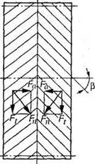
Fig.39. Efforts in engagement of chevron gears
These gears allow a large tooth angle (). Due to the complexity of manufacturing, chevron gears are used less frequently than helical gears, i.e. in cases where it is necessary to transmit high power and high speed, and axial loads are undesirable.

Rice. 40
Helical and chevron gears, unlike spur gears, have two pitches and two modules: in a normal section (see Fig. 44) along the pitch circle - normal pitch r p, in the end plane - end pitch p t . From the condition that the module of the link is equal to the step divided by the number, we have ; .
For helical and chevron wheels, normal modulus values t n standardized, since the profile of an oblique tooth in a normal section corresponds to the original contour of the tool rack and, therefore, T= t p(helical and chevron wheels are cut in the same way and with the same tool as straight teeth). Normal module t p is the starting point for geometric calculations.
Let us determine the relationship between the normal and end pitch and the module through the angle of inclination of the teeth.
If we divide the left and right sides by , we get
Geometric parameters of cylindrical helical and chevron gears with an involute tooth profile will be calculated using the formulas given in table. 15. According to the end module t t calculate the pitch (initial) diameters, and before t p- all other gear sizes.
Table 15. Geometric parameters of a cylindrical helical gear
| Parameter, designation | Calculation formulas | |
| Normal module | |
|
| End (circumferential module) | |
|
| Diameter of tooth tips in | |
|
| Pitch diameter d | |
|
| Tooth root diameter | ||
| Step is normal | ||
| End pitch (circumferential) | |
|
| Circumferential thickness of teeth | ||
| Tooth Gullet Width | ||
| Tooth height | ||
| Tooth head height | ||
| Tooth stem height | ||
| Radial clearance | ||
| Center distance | ||
| Tooth length | |
|
| Crown width |
District force .
An axial force acts on an oblique tooth (see Fig. 37), a radial (spacer) force ![]() .
.