GEAR MECHANISMS find the widest application in machines. They are used to change the angular velocity of the driven link. In this case, it is absolutely necessary to require a constant gear ratio not only for whole revolutions gear wheels, but also during the meshing of each pair of teeth. The condition that the tooth profiles must satisfy to maintain a constant gear ratio is determined by the gearing theorem, which states that the general normal AB to the gear profiles P1 and P2 at the point of contact K divides the CENTER-CENTRE DISTANCE O1 O2 INTO PARTS INVERSE PROPORTIONAL TO THE ANGULAR SPEED. The point of intersection of the normal and the center-to-center distance is called the POLE OF ENGAGEMENT (P) (Fig. I). So, gear ratio
where are the angular speeds of the wheels
Initial wheel circumferences
z 1 ,z 2 - number of wheel teeth.

In order for the gear ratio to be constant, it is necessary to choose a tooth profile for which, when a pair of teeth are engaged in any position, the engagement pole P retains its position on the line of centers. This condition is satisfied by the tooth profiles outlined by the involutes of circles.
Involute curve is called MOM1, described by point M of straight line NN, which rolls without sliding along a circle of radius rB=OA (Fig. 2). From the construction it is clear that the involute will be located outside the circle of radius rB and begins on this circle. The circle along which the straight line rolls is called the BASIC CIRCLE.
The involute equation in parametric form (angle parameter, Fig. 2) has the form
the radius vector of the involute is found from
where is the involute function
- pressure angle at radius level
The trigonometric function is called the involute of the angle, i.e. ![]()
Figure 8 shows the meshing of two teeth. The normal to the tooth profiles at the common point M of their contact passes through the pole P and, by the property of the involute, touches the main circles of the wheels. As the wheels rotate, the contact point M moves along this inner tangent, which is the engagement line. Pressure from wheel to wheel is transmitted along the engagement line at an angle to the line, which is a common tangent to the initial circles of the wheels. The angle is called the ENGAGEMENT ANGLE.
In Fig. Figure 4 shows part of a gear wheel. Side surfaces the teeth are outlined along the involute. The distance between the one-sided profiles of two adjacent gear teeth, taken along an arc, is called MESHING PITCH.
A DIVISION CIRCLE is a circle along which the step is equal to the standard step. The number of gear teeth - z must be an integer, so the engagement pitch must be a multiple of the length of the circle along which it is deposited. Therefore, if we denote by radius r - radius pitch circle wheel, P is the circumferential pitch along this circle and z is the number of teeth of the wheel, then equalities must take place.
The value m is the ratio of the circumferential pitch to the number, called the module of the teeth. The module is measured in millimeters and serves as the main parameter that determines the dimensions of the gear and its elements. The value of the module is defined by the standard.
A gear wheel is called ZERO if along the pitch circle the thickness of the tooth S is equal to the width of the cavity S B. The dimensions of the ELEMENTS of ZERO WHEELS, expressed in terms of the module, are given in the table.
| Wheel elements and engagement | Designation | Zero wheel |
| Engagement pitch | ||
| Pitch radius | ||
| Tooth head height | ||
| Tooth stem height | ||
| Protrusion circle radius | ||
| Radius of the circle of the depressions | ||
| Tooth thickness along pitch circle | ||
| Engagement angle | ||
| Core circle radius | ||
| Center distance |
When cutting gears using the rolling method, the tool is made either in the form of a wheel with involute tooth profiles (the so-called cutter), or a gear rack with straight tooth profiles (the so-called comb). In the process of cutting a gear, the workpiece and the tool are given the same relative motion as they would have if they were in mesh.
The tool has an additional reciprocating movement along the axis of the wheel, during which the cutting edge of the tool cuts a tooth profile on the workpiece.
From Fig. 5 it is clear that the rack pitch has the same value along any straight line (0-0 or I-I), parallel to the base slats. You can draw a 0-0 line along which the thickness of the tooth is equal to the width of the cavity. This line is called modular straight slats.
In order to cut a zero wheel, it is necessary to install the comb so that its modular straight line is removed from the center of the workpiece by the distance of the pitch circle radius r, i.e. so that the pitch circle of the workpiece is rolled without sliding along the modular straight line. Then the cut wheel will have teeth whose thickness along the pitch circle will be equal to the width of the cavity.
Let us move the rack away from the center of the wheel blank by an amount xm. Then, when cutting teeth, the pitch circle will roll without sliding along the line I-I, which we will call the initial straight line. It can be seen from the figure that in this case the thickness of the comb tooth on the initial straight line will be less than the cavity, which means that on the wheel being cut along the pitch circle the thickness of the tooth will be greater than the width of the cavity (since during running in the rack tooth forms a cavity on the workpiece). Gears cut by the rolling method with the comb removed from the center of the workpiece, in comparison with the zero setting, in which the pitch circle touches the modular straight line, are called POSITIVE WHEELS, and the additional removal of the comb is POSITIVE OFFSET (SHIFT). (Fig. 6).
You can give the comb a negative offset (shift), i.e. bring it closer to the center of the workpiece compared to the zero setting. Then an integer number of teeth will be cut on the workpiece with the outline of their side profile along the involute. However, in this case, along the pitch circle, the thickness of the tooth will be less than the width of the cavity. Such a wheel is called NEGATIVE. The ratio of displacement to modulus is called DISPLACEMENT RATIO (RELATIVE SHIFT) and is denoted by x.
The production of positive, so-called corrected, wheels is carried out in order to increase the strength of the teeth (eliminate undercutting of the small wheel profile), reduce highest values specific slip.
Corrected wheels can be inserted into clutches with each other and with zero wheels. Formulas for calculating the elements of corrected wheels and their engagement are given in Table 1.
Laboratory work No. 10
Profiling of involute teeth
Purpose of the work: mastering the technique of cutting involute gears using the rounding (running in) method with various tool offsets; calculation of the geometry of involute gearing.
Equipment: device for profiling teeth TMM-42, device for cutting paper circles, paper circle, sharpened pencil.
Brief theoretical information
The bending method in the manufacture of involute gears
Gears are made in two main ways: copying and bending. The most advanced in profile accuracy and performance is bending method(Fig. 10.1). When manufacturing a wheel using this method, its tooth profiles are formed as envelopes to the family of positions of the tooth profiles of the producing wheel (tool). If the producing wheel has teeth with an involute profile (cutter, Fig. 10.1, A), then on the workpiece, as a result of processing by this method, teeth are also obtained with involute profiles. With a wheel radius equal to infinity, the instrument is transformed into a rack with straight tooth profiles (comb, 10.1, b). Such tool tooth profiles are simple and technologically advanced, allowing the production of tools with high precision. The most highly productive method is cutting gears with a modular hob cutter(Fig. 10.1, V).
Enveloping method allows the same tool to cut wheels with different numbers of teeth and various forms tooth profile, which are determined not only by the size of the tool, but also by its location relative to the workpiece. The geometric parameters of the cut cylindrical wheel are determined by the module m and parameters of the standard initial contour according to GOST 13755: profile angle α = 20º; tooth head height coefficient = 1; radial clearance coefficient With*= 0.25; transition curve radius coefficient = 0.38 (Fig. 10.2).

Rice. 10.2. Initial contours
Given coefficients multiplied by modulus T, give geometric parameters expressed by the same symbols without asterisks. Depending on how the pitch line from the tool is located in relation to the pitch circle of the wheel being cut, you get zero, positive and negative gears. Displacement ξ = xt is the distance from the pitch line of the tool to the pitch circle of the wheel, x - displacement coefficient.
Zero gear cut without displacement, that is xm= 0 and x = 0
(Fig. 10.3). In a machine gear, the initial ones are the pitch line of the tool and the pitch circle of the wheel. Since they roll over each other without slipping, then on the pitch circle of zero
wheel thickness of the tooth is equal to the width of the cavity:

Rice. 10.3. Zero wheel cutting
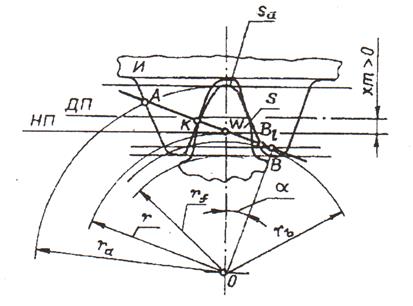
Positive gear with bias factor xt > 0 (Fig. 10.4) is obtained when the tool is displaced in the radial direction from the center of the workpiece . On the pitch circle of a wheel with a positive offset, the thickness of the tooth is greater than the width of the cavity and is equal to:
Due to an increase in the pitch thickness of the tooth the leg becomes thicker and the bending strength of the tooth increases.
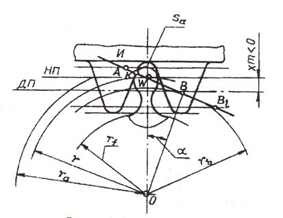
Negative gear with bias factor X< 0 (Fig. 10.5) is obtained if the tool is moved from the zero position to the center of the wheel being cut. For a wheel with negative offset s< e. The pitch thickness of the tooth is determined by formula (10.3), in which the displacement coefficient x enters with a minus sign.
Rice. 10.4. Positive wheel cutting
Rice. 10.5. Negative wheel cutting
Trimming the teeth of an involute gear
Active engagement line AB 1(Fig. 10.3) are determined by the points of intersection of the machine engagement line with the circle of the vertices and the straight line of the boundary points. Changing the tool offset value also changes the position of the point B 1 on the engagement line. If the point B 1 will go outside the line AB, which determines the contact zone of the mating profiles of the tool and the wheel, then the tooth will be cut. At the same time the tool cuts off part of the main profile, reducing the thickness of the tooth at the base and reducing its bending strength. The profiles of the cut part of the tooth will not be involute, resulting in the main linking theorem will be violated. The degree of tooth cutting depends on the amount of displacement, the parameters of the generating circuit and the number of teeth of the wheel. For a zero wheel, the minimum number of teeth cut without trimming is determined by the formula:
In formula (10.5) the number of teeth< 17. Из вышеизложенного можно сделать conclusions:
In the zero wheel, cutting will not occur when z ≥ 17;
There are three possible options for positioning the center line of the tool rack relative to the pitch circle of the wheel.
1. Average direct productivity contour C-C touches the pitch circle of the workpiece (Fig. 35 b). The center line rolls without sliding along a pitch circle equal to the width of the recess of the rack along the center line. . This wheel is called an equal pitch wheel.
2. Medium line S-S shifted (raised) by an amount, where X is the displacement coefficient (Fig. 1.35 a). The initial circle H-H, separated from the middle straight line by . The thickness of the tooth along the pitch circle turns out to be greater than the width of the cavity, which corresponds to an increase in the width of the cavity of the generating contour of the initial straight line H-H. From the pictures it follows:
The displacement coefficient X in this case is considered positive.
3. Medium straight S-S is shifted to the center by an amount Xm, and the displacement coefficient X is considered negative (Fig. 1.35 c).
The thickness of the tooth along the pitch circle is also determined by formula (1.14) and due to the fact that , turns out to be less than that of a wheel with an equally divided pitch.
Gears cut with rack shear are called straightened gears. Wheels cut with a positive shear are called positive. And those sliced with a negative shift are negative. Wheels cut without shearing are called zero wheels.
In order to determine which of these groups a gear belongs to, it is necessary to determine the thickness of its teeth along the pitch circle.
Depending on the displacements of each wheel, three types of gears can be obtained, differing in the location of the initial and pitch circles.
Type I(Fig. 1.36 a). These circles coincide, if the transmissions satisfy the condition, the transmission is called zero,
that is, gears made up of wheels without displacement and gears in which the negative displacement of one wheel is equal to absolute value positive displacement of the other wheel (equally offset).
The center distance in these gears is called the pitch center distance, and the engagement angle equal to angle profile of the generating circuit.
Type II(Fig. 1.36 b). In gears in which, along the pitch circles, the thickness of the tooth of one wheel is greater than the width of the cavity of the other, for engagement without lateral play, the center-to-center distance must be greater than a.
The angle increases accordingly.
III type(Fig. 1.36 c). Similarly, for gears in which the thickness of the teeth of one of the wheels along the pitch circle is less than the cavity of the other, we have. These transfers are obtained when
Geometric calculation gears at given offsets X 1 and X 2
To calculate and first determine the thickness of the tooth along the initial circle.
From (Fig. 1.37) taking into account the involute equation we have:
Substituting the value of the tooth thickness along the pitch circle:
and considering
AND ![]() ,
,
where is the step along the initial circle we get:
For initial circles, the sum of the tooth thicknesses is equal to the pitch
![]()
Hence, taking into account formula (1.15)
we determine from the table.
We determine the radii of the initial circles from