Mechanisms with lower pairs (lever mechanisms), the synthesis of which was discussed in previous chapters, ensure the transmission of significant forces, since the links of the pair are in contact along the surface. But the condition of constant contact on the surface limits the number possible types lower pairs The mechanisms use only six types of lower pairs: rotary, translational, screw, cylindrical, spherical and planar. Therefore, many practically important laws for transforming the movement of links cannot be obtained through mechanisms that have only lower pairs. Mechanisms containing higher pairs have significantly greater possibilities for reproducing almost any law of motion, since the conditions for contacting the interacting surfaces of the links of the higher pair along lines and points can be met for countless different surfaces (Fig. 6.1).
The interacting surfaces of the links of the higher pair, ensuring the given law of their relative motion, are called conjugate surfaces. When reproducing the return motion, it is possible to have one pair of mating surfaces (for example, in cam mechanisms). If it is necessary to reproduce continuous movement in one direction, then it is necessary to have several sequentially interacting pairs of mating surfaces, which are located on protrusions called teeth.
The highest kinematic pair formed by sequentially interacting tooth surfaces is called gearing. The term “engagement” (without adding the word “toothed”) can also be applied to one pair of mating surfaces. It is then synonymous with the term "top pair".

Gears are the most common transmissions in machine and instrument drives. They are used to transmit motion over a wide range of powers (up to 300 MW) and speeds (up to 200 m/s). They have a number of significant advantages: they have relatively small dimensions, at any moment the gear ratio is maintained constant (round wheels) or varies according to a given law (non-round wheels), efficiency gears quite high (up to 0.97 - 0.99 for one set of mating wheels - one gear stage). They are highly reliable.
The disadvantages of gears are due to the relatively complex technology of manufacturing gears and the appearance of noise when the gear operates at high speeds.
Classification of gears produced according to geometric and functional characteristics.
According to the relative position of the geometric axes, gears are divided into gears with:
Parallel axes (cylindrical Fig. 6.2 a, b, c, d);
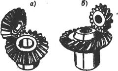
Intersecting axes (conical, Fig. 6.3);
With axes crossing in space (hyperboloid: worm (Fig. 6.5), screw (Fig. 6.2d), hypoid (Fig. 6.4).

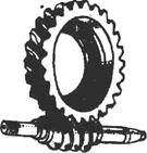
Fig.6.4 Fig.6.5
Depending on the location of the teeth relative to the forming body of the workpiece, gear drives are divided into:
Straight teeth (cylindrical (Fig. 6.2a, e) and conical (Fig. 4.3a)):
Helical (Fig. 6.2b);
Chevron (cylindrical only, Fig. 6.2c);
With a curved tooth (Fig. 6.2d, 6.3b, 6.4, 6.5).
The gear engagement may be external(Fig.6.6), internal(Fig. 6.7) and rack and pinion(Fig. 6.8).
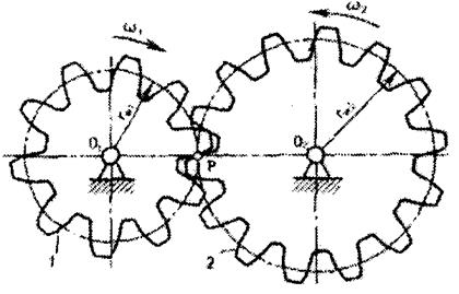
External gear- gearing, in which the axial surfaces of gears 1 and 2 are located one outside the other. In Fig. 6.6 the end section cylindrical gear with external wheel engagement. Axoidal surfaces of radii ŕ ŵ1 and ŕ ŵ2 are in contact. R. The wheels rotate in opposite directions with angular speeds ω 1 and ω 2, inversely proportional to the radii ŕ ŵ1 and ŕ ŵ2 or the number of teeth z 1 and z 2. External gearing is the most common in gears due to the simplicity of the device and the manufacturability of such gears. Gears that form external gears are called wheels with external teeth.
Internal gear- gearing, in which the axial surfaces of the gears are located one inside the other. Figure 6.7 shows the end section of a cylindrical gear with internal gearing.

Axoidal surfaces are characterized by radii ŕ ŵ1 and ŕ ŵ2 and are in contact at the point of rotation. The wheels rotate in the same directions with angular velocities ω 1 and ω 2, inversely proportional to the radii ŕ ŵ1 and ŕ ŵ2 or the number of teeth z 1 and z 2 . Due to the complexity of manufacturing the gear, internal gearing is less common than external gearing. It is usually used in planetary gears, machine platform rotation mechanisms, and other cases. Gears with internal gears, compared to gears with external gears, are smaller in size and weight, and are characterized by smoother operation due to a higher overlap coefficient and contact of convex and concave tooth surfaces with a large reduced radius of curvature and lower sliding speeds. Gear 2 with outer axoidal surface and a large number teeth is called a wheel with internal teeth, and the wheel 1 associated with it is a wheel with external teeth.
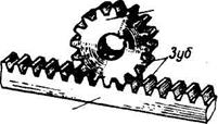
IN rack and pinion The radius of curvature of the initial circle of the wheel is equal to infinity (Fig. 6.8). This gearing is used to convert rotational motion into translational motion.
Depending on the nature of the relative movement of the wheels, gears are distinguished:
With fixed geometric wheel axles (regular or ordinary gears);
Planetary and differential gears, in which the axis is at least
one wheel is movable in space.
In rolling stock railways, as in other machines, gears can be power (for example, the traction gear of a locomotive) or non-power (for example, a gear in a speedometer drive).
Questions for self-control:
1. What are the main advantages and disadvantages of gears?
2. What is it like relative position geometric axes of wheels in cylindrical, bevel and hyperboloid gears?
3. How do gear drives differ in the location of the teeth relative to the forming body of the wheel blank?
4. What is the difference between external, internal and rack gears?
5. Name the difference between ordinary and planetary gears.
Introduction
- 1 Spur gears
- 1.1 Transverse tooth profile 1.2 Longitudinal tooth line
- 1.2.1 Spur gears 1.2.2 Helical gears 1.2.3 Chevron wheels
- 6.1 Run-in method
- 6.1.1 Running-in method using a comb 6.1.2 Running-in method using a hob cutter 6.1.3 Running-in method using a cutter
- 7.1 Trimming the tooth 7.2 Sharpening the tooth
Literature
Introduction
Gears
Gear?, gear?- the main part of a gear transmission in the form of a disk with teeth on a cylindrical or conical surface that mesh with the teeth of another gear. In mechanical engineering, it is customary to call a small gear with fewer teeth gear, and the big one is a wheel. However, all gears are often called gears.
Operation of spur gear
Gears are usually used in pairs with different numbers teeth in order to convert the torque and number of revolutions of the input and output shafts. A wheel to which torque is supplied externally is called leading, and the wheel from which the moment is removed is slave. If the drive wheel diameter less, then the torque of the driven wheel increases due to proportional decrease rotation speed, and vice versa. According to gear ratio, an increase in torque will cause a proportional decrease in the angular speed of rotation of the driven gear, and their product - mechanical power - will remain unchanged. This relationship is valid only for the ideal case, which does not take into account friction losses and other effects characteristic of real devices.
Movement of the point of contact of the teeth with the involute profile;
left - driving wheel, right - driven wheel
Gear hydraulic machine
1. Spur gears
Gear parameters
1.1. Transverse tooth profile
The wheel tooth profile usually has an involute side shape. However, there are gears with a circular tooth profile (Novikov gear with one and two lines of engagement) and with a cycloidal one. In addition, ratchet mechanisms use gears with an asymmetrical tooth profile.
Involute gear parameters:
- m- wheel module, dark and light wheels have the same module. The most important parameter, standardized, is determined from the strength calculation of gears. The more loaded the transmission, the higher the module value. All other parameters are expressed through it. The module is measured in millimeters and is calculated using the formula:
- z- number of wheel teeth p- tooth pitch (marked in purple) d- diameter of the pitch circle (marked in yellow) da- diameter of the circle of the vertices of the dark wheel (marked in red) db- diameter of the main circle - involute (marked green) df- diameter of the circle of the dark wheel depressions (marked in blue) haP+hfP- height of the dark wheel tooth, x+haP+hfP- light wheel tooth height
In mechanical engineering, certain values of the gear module are accepted m for ease of manufacture and replacement of gears, which are integers or numbers with decimal: 1 ; 1,25 ; 1,5 ; 1,75 ; 2 ; 2,5 ; 3 ; 3,5 ; 4 ; 4,5 ; 5 and so on until 50 .
Tooth head height - haP and the height of the tooth stem - hfP- in the case of the so-called zero gear (made without offset, gear with "zero" teeth)(the displacement of the cutting rack, cutting the teeth, closer or further to the workpiece, and the displacement closer to the workpiece is called positive bias, and the displacement further from the workpiece is called. negative) correspond to the module m as follows: haP = m; hfP = 1.2 m, that is:
From this we obtain that the tooth height h(not indicated in the figure):
In general, it is clear from the figure that the diameter of the circle of the vertices da greater than the diameter of the circle of the depressions df to double tooth height h. Based on all this, if you need to practically determine the module m gear, without the necessary data for calculations (except for the number of teeth z), then it is necessary to accurately measure its outer diameter da and divide the result by the number of teeth z plus 2:
1.2. Longitudinal line of the tooth
Spur wheels
1.2.1. Spur wheels
Gear wheel from a clock mechanism
Spur gears are the most common type of gears. The teeth are located in radial planes, and the contact line of the teeth of both gears is parallel to the axis of rotation. In this case, the axes of both gears must also be located strictly parallel.
Helical wheels
1.2.2. Helical wheels
Helical gears are an improved version of spur gears. Their teeth are located at an angle to the axis of rotation, and their shape forms part of a spiral. The engagement of such wheels occurs more smoothly than straight teeth and with less noise.
- When a helical gear operates, a mechanical force arises directed along the axis, which necessitates the use of thrust bearings to install the shaft; An increase in the friction area of the teeth (which causes additional power losses due to heating), which is compensated by the use of special lubricants.
Chevron wheels
In general, helical wheels are used in mechanisms that require the transmission of high torque at high speeds, or have strict noise restrictions.
1.2.3. Chevron wheels
Chevron wheels solve the problem of axial force. The teeth of such wheels are made in the form of the letter “V” (or they are obtained by joining two helical wheels with opposing teeth). The axial forces of both halves of such a wheel are mutually compensated, so there is no need to install the shafts on thrust bearings. In this case, the transmission is self-aligning in the axial direction, which is why in gearboxes with chevron wheels one of the shafts is mounted on floating supports (usually on bearings with short cylindrical rollers). Transfers based on such gear wheels, usually called "chevron".
Sector gear with internal gearing
1.3. Internal gears
With strict restrictions on dimensions, in planetary mechanisms, in gear pumps with internal gearing, in the drive of a tank turret, wheels with ring gear, sliced with inside. The driving and driven wheels rotate in one direction. In such a transmission there are less friction losses, that is, higher efficiency.
1.4. Sector wheels
A sector wheel is a part of any type of regular wheel. Such wheels are used in cases where the link does not need to rotate a full turn, and therefore you can save on its dimensions.
1.5. Wheels with circular teeth
A transmission based on wheels with circular teeth (Novikov Transmission) has even higher driving performance than helical ones - high load capacity of engagement, high smoothness and quiet operation. However, they are limited in their use by reduced, under the same conditions, efficiency and service life; such wheels are noticeably more difficult to produce. Their line of teeth is a circle of radius, selected for certain requirements. The contact of the tooth surfaces occurs at one point on the engagement line, located parallel to the wheel axes.
2. Bevel gears
Conical wheels in the dam gate drive
In many machines, the implementation of the required movements of the mechanism is associated with the need to transmit rotation from one shaft to another, provided that the axes of these shafts intersect. In such cases, bevel gears are used. There are types of bevel wheels that differ in the shape of the tooth lines: with straight, tangential, circular and curved teeth. Straight-toothed bevel wheels, for example, are used in automobile differentials, used to transfer torque from the engine to the wheels.
3. Rack and pinion transmission (rack)
Rack and pinion transmission
Roman Abt system (German) Roman Abt), used in cogwheel railways
Rack and pinion transmission (rack and pinion) is used in cases where it is necessary to convert rotational motion into translational motion and vice versa. It consists of a conventional spur gear and a toothed bar (rack). The operation of such a mechanism is shown in the figure.
A rack is a part of a wheel with an infinite pitch circle radius. That's why pitch circle, as well as the circles of the peaks and valleys turn into parallel straight lines. The involute profile of the rack also takes on a rectilinear shape. This property of the involute turned out to be most valuable in the manufacture of gears.
Rack and pinion transmission is also used in cogwheel railways.
Pinwheel transmission
Ring gear
4. Crown wheels
A crown wheel is a special type of wheel whose teeth are located on the side surface. Such a wheel is usually connected to a regular spur wheel, or to a drum made of rods (lantern wheel), as in a tower clock.
5. Others
6. Manufacturing of gears
Run-in method
6.1. Run-in method
Currently, it is the most technologically advanced, and therefore the most widespread, method of manufacturing gears. In the manufacture of gears, tools such as a comb, hob cutter and cutter can be used.
6.1.1. Run-in method using a comb
Cutting a gear using the rolling method on a gear hobbing machine using a hob cutter
Hob
A cutting tool shaped like a rack is called a comb. On one side of the comb, the cutting edge is sharpened along the contour of its teeth. The blank of the wheel to be cut makes rotational movement around the axis. The comb makes a complex movement, consisting of a translational movement perpendicular to the wheel axis and a reciprocating movement (not shown in the animation) parallel to the wheel axis to remove chips across the entire width of its rim. The relative motion of the comb and the workpiece can be different, for example, the workpiece can perform an intermittent complex rolling movement, coordinated with the cutting movement of the comb. The workpiece and the tool move relative to each other on the machine as if the profile of the cut teeth is engaged with the original producing contour of the comb.
6.1.2. Run-in method using a hob cutter
In addition to the comb as cutting tool use a hob cutter. In this case, a worm gear occurs between the workpiece and the cutter.
6.1.3. Run-in method using a cutter
Gears are also chiseled on gear shaping machines using special cutters. A gear shaper is a gear wheel equipped with cutting edges. Since it is usually impossible to cut off the entire metal layer at once, processing is carried out in several stages. During processing, the tool makes a reciprocating movement relative to the workpiece. After each double stroke, the workpiece and the tool rotate relative to their axes by one step. Thus, the tool and the workpiece seem to “run” against each other. After the workpiece has made a full revolution, the cutter makes a feed motion towards the workpiece. This process continues until the entire required layer of metal is removed.
6.2. Copy method (Divide method)
A disc or finger cutter is used to cut one tooth cavity of the gear. The cutting edge of the tool is shaped like this depression. After cutting one cavity, the workpiece is rotated one angular step using a dividing device, and the cutting operation is repeated.
The method was used at the beginning of the 20th century. The disadvantage of this method is its low accuracy: the cavities of a wheel made using this method are very different from each other.
6.3. Hot and cold rolling
The process is based on the sequential deformation of a layer of a workpiece heated to a plastic state at a certain depth using a gear-rolling tool. This combines induction heating of the surface layer of the workpiece to a certain depth, plastic deformation of the heated layer of the workpiece to form teeth, and rolling of the formed teeth to obtain a given shape and accuracy.
6.4. Manufacturing of bevel wheels
The manufacturing technology of bevel wheels is closely related to the geometry of the side surfaces and tooth profiles. The method of copying the shaped profile of a tool to form a profile on a bevel wheel cannot be used, since the dimensions of the cavity of the bevel wheel change as it approaches the apex of the cone. In this regard, tools such as a modular disc cutter, a finger cutter, or a shaped grinding wheel can only be used for rough cutting of cavities or for the formation of wheel cavities no higher than the eighth degree of accuracy.
To cut more precise bevel wheels, use the method of running in the machine engagement of the cut workpiece with an imaginary producing wheel. Side surfaces producing wheels are formed due to the movement of the cutting edges of the tool during the main cutting movement, which ensures cutting off the allowance. Tools with a straight blade became more widespread. With a straight main movement, a straight blade forms a flat producing surface. Such a surface cannot form an involute conical surface with spherical involute profiles. The resulting conjugate conical surfaces, which differ from involute surfaces, are called quasi-involute.
6.5. Modeling
Modeling (cont. 1m35s) another version.
7. Mistakes when designing gears
Tooth cut at the base
Tooth trimming
7.1. Tooth trimming
According to the properties of involute gearing, the straight part of the initial generating contour of the gear rack and the involute part of the tooth profile of the cut wheel touch only on the machine gearing line. Beyond this line, the original generating contour intersects the involute profile of the wheel tooth, which leads to the cutting of the tooth at the base, and the cavity between the teeth of the cut wheel becomes wider. Trimming reduces the involute part of the tooth profile (which leads to a reduction in the duration of engagement of each pair of teeth of the designed gear) and weakens the tooth in its dangerous section. Therefore, pruning is unacceptable. To prevent undercutting from occurring, geometric restrictions are imposed on the wheel design, from which the minimum number of teeth is determined at which they will not be undercut. For a standard tool, this number is 17. Undercutting can also be avoided by using a gear manufacturing method other than the running-in method. However, even in this case, the conditions for the minimum number of teeth must be observed, otherwise the depressions between the teeth of the smaller wheel will turn out to be so tight that the teeth larger wheel the manufactured gear will not have enough space for them to move and the gear will jam.
Sharpening the tooth
To reduce the overall dimensions of gears, wheels should be designed with a small number of teeth. Therefore, when the number of teeth is less than 17, in order to avoid undercutting, the wheels must be made with a tool offset - increasing the distance between the tool and the workpiece.
7.2. Sharpening the tooth
As the tool offset increases, the tooth thickness will decrease. This leads to sharpening of the teeth. The risk of sharpening is especially high for wheels with a small number of teeth (less than 17). To prevent chipping of the top of a pointed tooth, the displacement of the tool is limited from above.
Literature
Ed. Skorokhodova E. A. General technical reference book. - M.: Mechanical Engineering, 1982. - P. 416. Gulia N. V., Klokov V. G., Yurkov S. A. Machine parts. - M.: Publishing Center "Academy", 2004. - P. 416. - ISBN -5 Bogdanov V.N., Malezhik I.F., Verkhola A.P. et al. A Reference Guide to Drawing. - M.: Mechanical Engineering, 1989. - P. 438-480. - 864 p. - ISBN -7 Handbook of mechanical engineering designer: In 3 volumes / Ed. I. N. Zhestkova. - 8th ed., revised. and additional.. - M.: Mashinostroenie, 2001. - T. 2. - 912 p. - ISBN 5), BBK 34.42ya2, UDC 621.001 Frolov K.V., Popov S.A., Musatov A.K., Timofeev G.A., Nikonorov V.A. Theory of mechanisms and mechanics of machines / Kolesnikov K. S. - Fourth edition, corrected and expanded. - M.: Publishing house of MSTU im. N. E. Bauman, 2002. - T. 5. - P. 452-453, 456-459, 463-466, 497-498. - 664 s. - (Mechanics at a technical university). - 3000 copies. - ISBN -8 Leonova L. M., Chigrik N. N., Tataurova V. P. Gear transmissions. Elements of calculation and design: Guidelines. - Omsk: Omsk State Technical University Publishing House, 2005. - 45 p.The module m and the number of teeth z are the main quantities that determine gearing. The value of the modules for all gears is a standardized value, expressed, as can be seen from the formula m = d/z, in millimeters. Below are the numerical values of standard modules used in the manufacture of gears, according to GOST 9563-60 (ST SEV 310-76):
1st row, mm: 0,05; 0,06; 0,08; 0,1; 0,12; 0,15; 0,2; 0,25; 0,3; 0,4; 0,5; 0,6; 0,8; 1; 1,25; 1,5; 2; 2,5; 3; 4,5; 6; 8; 10; 12; 16; 20; 25; 32; 40; 50; 60; 80; 100.
2nd row, mm: 0,055; 0,07; 0,09; 0,11; 0,22; 0,28; 0,35; 0,45; 0,55; 0,7; 0,9; 1,125; 1,375; 1,75; 2,25; 2,75; 3,5; 4,5; 5,5; 7; 9; 11; 14; 18; 22; 28; 36; 45; 55; 70; 90.
When assigning modulus values, the first row should be preferred to the second.
Gear transmissions. General information and classification of gears
A mechanism in which two moving links are gearedscaffolding that forms a rotary or feeder with a fixed linkThis pair is called a gear train(Fig. 1).
Rice. 1. Types of gears:a, b, c - spur gears with externalengagement;G - rack and pinion transmission;d - cylindrical gear with internal gearing;e - gear helical gear;g, h, i - bevel gears; k-giPoid transmission
In most cases, a gear train serves to transmit rotational motion. In some mechanisms, this transmission is used to convert rotational motion into translational motion (or vice versa, see Fig. 1, G).
Gear drives are the most common type of gears in modern mechanical engineering and instrument making; they are used in wide ranges of speeds (up to 275 m/s) and powers (up to tens of thousands of kilowatts).
Main advantages of gears compared to other transmissions:
Manufacturability, constant gear ratio;
High load capacity;
High efficiency (up to 0.97-0.99 for one pair of wheels);
Small overall dimensions compared to other types of gears under equal conditions;
Greater operational reliability, ease of maintenance;
Relatively low loads on shafts and supports.
Disadvantages of gears should include:
Inability to continuously change the gear ratio;
High requirements for precision manufacturing and installation;
Noise at high speeds; poor shock-absorbing properties;
Bulkyness at large distances between the axes of the drive and driven shafts;
The need for special equipment and tools for cutting teeth;
The gear drive does not protect the machine from possible dangerous overloads.
Gears and wheels are classified according to the following characteristics(see Fig. 1):
According to the relative position of the wheel axes - with parallel axes (cylindrical, see Fig. 1, hell), with intersecting axes (conical, see Fig. 1, f-i), with crossing axes (screw, see Fig. 1, e, To);
According to the location of the teeth relative to the forming wheels - straight, helical, chevron and with a curved tooth;
By design - open and closed;
By circumferential speed - low-speed (up to 3 m/s), for medium speeds (3-15 m/s), high-speed (over 15 m/s);
According to the number of stages - single- and multi-stage;
According to the location of the teeth in the gear and wheels - external, internal (see Fig. 1, d) and rack and pinion gearing (see Fig. 1, d);
According to the shape of the tooth profile - involute, circular;
According to the accuracy of engagement. The standard provides 12 degrees of accuracy. In practice, gears for general mechanical engineering are manufactured from the sixth to the tenth degree of accuracy. Gears manufactured to the sixth degree of accuracy are used for the most critical cases.
Of the gears listed above, the most widely used are cylindrical spur And helical transmissions, as the simplest to manufacture and operate.
Gears with involute profile teeth, which are produced by the mass rolling method on gear hobbing or gear shaping machines, have become predominant. The advantage of involute gearing is that it is little sensitive to fluctuations in the center-to-center distance.
Other types of gearing are still used to a limited extent. Thus, cycloidal gearing, in which the operation of gears with a very small number of teeth (2-3) is possible, cannot, unfortunately, be manufactured by the modern high-performance rolling-in method, therefore the gears of this gearing are labor-intensive to manufacture and expensive; Novikov's new spatial gearing has not yet received widespread distribution, due to its high sensitivity to fluctuations in the center-to-center distance.
Spur gears (about 70%) are used at low and medium speeds, when dynamic loads from manufacturing inaccuracies are small, in planetary, open gears, as well as when axial movement of the wheels is necessary.
Helical wheels (more than 30%) have greater smoothness and are used for critical mechanisms at medium and high speeds.
Chevron wheels have the advantages of helical wheels plus balanced axial forces and are used in highly loaded gears.
Bevel gears are used only in cases where this is necessary according to the conditions of the machine layout; screw - only in special cases.
Internal gears rotate in the same directions and are usually used in planetary gears.
Surfaces that mesh with the teeth of another gear. In mechanical engineering, it is customary to call a small drive gear, regardless of the number of teeth gear, and the large driven one is a wheel. However, all gears are often called gears.
Gears are usually used in pairs with different numbers of teeth to convert torque and output shaft speed. The wheel to which the torque is supplied from the outside is called the driving wheel, and the wheel from which the torque is removed is called the driven wheel. If the diameter of the drive wheel is smaller, then the torque of the driven wheel increases due to a proportional decrease in the rotation speed, and vice versa.
It should be noted that the gear train is not a mechanical power amplifier, since total quantity the mechanical energy at its output cannot exceed the amount of energy at its input. This is due to the fact that mechanical work in this case will be proportional to the product of torque and rotation speed. In accordance with the gear ratio, an increase in torque will cause a proportional decrease in the angular speed of rotation of the driven gear, and their product will remain unchanged. This relationship is valid for the ideal case, which does not take into account friction losses and other effects characteristic of real devices.
Transverse tooth profile
Movement of the point of contact of the teeth with the involute profile
The lateral shape of the wheel tooth profile to ensure smooth rolling can be: involute, non-involute Novikov gear (with one or two lines of engagement), cycloidal. In addition, ratchet mechanisms use gears with an asymmetrical tooth profile.
Longitudinal line of the tooth
Spur wheels

Operation of spur gear
Spur gears are the most common type of gears. The teeth are a continuation of the radii, and the contact line of the teeth of both gears is parallel to the axis of rotation. In this case, the axes of both gears must also be located strictly parallel.
Helical wheels
Helical gears are an improved version of spur gears. Their teeth are located at an angle to the axis of rotation, and their shape forms part of a spiral. The engagement of such wheels occurs more smoothly than straight teeth and with less noise.
- When a helical gear operates, a mechanical moment occurs directed along the axis, which necessitates the use of thrust bearings to install the shaft;
- An increase in the friction area of the teeth (which causes additional power losses due to heating), which is compensated by the use of special lubricants.
In general, helical gears are used in mechanisms that require the transmission of large torque at high speed, or have strict noise restrictions.
Wheels with circular teeth
Gears based on wheels with circular teeth have even higher driving performance than helical gears - high smoothness and quiet operation. However, they are limited in application due to reduced, under the same conditions, efficiency and service life; such wheels are noticeably more difficult to produce. Their line of teeth is a circle of radius, selected for certain requirements.
Double helical wheels (chevrons)
Double helical wheels solve the problem of axial moment. The teeth of such wheels are made in the form of the letter “V” (or they are obtained by joining two helical wheels with opposing teeth). Axial moments Both halves of such a wheel are mutually compensated, so there is no need to install axles and shafts in special bearings. Transmissions based on such gears are usually called “chevron”.
Toothed bevel wheels

Conical wheels in the dam gate drive
In addition to the most common cylindrical gears, conical wheels are used. Bevel wheels are used where it is necessary to transmit torque at a certain angle. Such bevel wheels with a circular tooth, for example, are used in automobile differentials, used to transmit torque from the engine to the wheels.
Sector wheels
Sector gear with internal gearing
A sector wheel is a part of any type of regular wheel. Such wheels are used in cases where 360° rotation of the mechanism is not required, and therefore you can save on its dimensions.
Internal gears
With strict restrictions on dimensions, in planetary mechanisms, in gear pumps with internal gearing, in the drive of a tank turret, it is convenient to use wheels with a ring gear cut from the inside. It is also worth noting that the rotation of the drive and driven wheels is directed in the same direction. In such a transmission there is less friction loss, i.e. higher efficiency.
Rack and pinion transmission
Literature
- Ed. Skorokhodova E. A. General technical reference book. - M.: Mechanical Engineering, 1982. - P. 416.
- Gulia N. V., Klokov V. G., Yurkov S. A. Machine parts. - M.: Publishing Center "Academy", 2004. - P. 416. - ISBN 5-7695-1384-5
- Bogdanov V.N., Malezhik I.F., Verkhola A.P. et al. Reference Guide to Drawing. - M.: Mechanical Engineering, 1989. - P. 438-480. - 864 p. - ISBN 5-217-00403-7
- Anuriev V.I. Handbook of mechanical engineering designer. In 3 vols. - M.: Mechanical Engineering, 2001. - ISBN 5-217-02962-5
Wikimedia Foundation. 2010.