Geometric parameters. For helical gears, the teeth are located at a certain angle to the generatrix of the dividing cylinder (Figure 11.9). The axles of the wheels remain parallel. For cutting oblique teeth, use a tool of the same initial profile as for cutting straight teeth. Therefore, the contour of an oblique tooth in normal section n-n coincides with the contour of a straight tooth. The module in this section is standard

Figure 11.9 - Scheme helical cylindrical gear(geometric dimensions)
End section t-t the parameters of the oblique tooth vary depending on the value of the angle p:
District step.
District module.
Pitch diameter ![]() .
.
Index n are assigned to the parameters in the normal section, and the index t attributed to the parameters in the end section.
The section normal to the tooth forms an ellipse with semiaxes
c=r And e=, Where . The teeth located on the minor axis of the ellipse are engaged, since the second wheel is at a distance .
The radius of curvature of the ellipse on the minor axis (see geometry) ![]() .
.
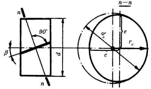
Figure 11.10 - Scheme for determining the equivalent parameters of helical spur gears
In accordance with this, the shape of an oblique tooth in normal section is equivalent to a spur gear, the diameter of which is
and number of teeth
![]()
Increase in equivalent parameters (d v And zv) increases strength with increasing angle helical gears.
Multi-pair and smooth engagement. Unlike straight teeth, oblique teeth do not engage immediately along the entire length, but gradually. The engagement moves away from the points 1 to the points 2 (Figure 11.9).
The location of the contact lines in the field of helical gearing is shown in Figure 11.11, a, b (compare with Figure 11.3 - spur gearing). When moving, the contact lines move in the engagement field in the direction shown by the arrow. At the considered moment of time, there are three pairs of teeth in engagement 1, 2 and 3. Pair 2 is engaged along the entire length of the teeth, and a pair 1 And 3 – only partially. Then pair 3 disengages and moves to position 3", and there are still two pairs in engagement 2" And 1’. Unlike spur gearing, helical gearing does not have a single-pair gearing zone. In spur gearing, the load from two teeth to one or from one to two is transferred instantly.
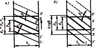
Figure 11.11 - Multi-pair helical gearing
This is accompanied by shock and noise. In helical gears, the teeth are loaded gradually as they enter the meshing field, and there are always at least two pairs of teeth in mesh. Smooth helical gearing significantly reduces noise and dynamic loads.
Helical gears can operate without loss of engagement even with an end overlap ratio< 1, если обеспечено осевое перекрытие b w >;(Figure 11.11, b) . Attitude
![]() (11.22)
(11.22)
is called the axial overlap coefficient. It is recommended to take ≥ 1.1. IN helical gearing the load is distributed over the entire total length of the contact lines 1, 2, 3. The specific load decreases with an increase in the total length of the contact lines. From Figure 11.11, it can be established that when equal to whole number,
and does not change when moving, since the decrease in the line 3 always corresponds to an equal increase in the line 1. From formula 11.23 it can be seen that it grows with an increase, which is beneficial. However, with an increase, the axial loads in the engagement increase (see below), therefore it is recommended to take = 8 - 20 °.
On the lateral surface of the oblique tooth, the contact line is located at a certain angle (Figure 11.12, a). Angle , increases with . The load is unevenly distributed along the contact line. Its maximum is on the midline of the tooth, since when engaged by the middle, the teeth have the maximum total rigidity.
When the tooth moves in the engagement plane, the contact line moves in the direction from 1 To 3 (Figure 11.12, b), while the position may be dangerous for strength 1, in which the corner of the tooth breaks off. A fatigue crack is formed at the root of the tooth at the point of stress concentration and then propagates at some angle. The probability of an oblique fracture is reflected in the strength of the teeth in terms of bending stresses, and the load concentration q– for contact stress strength.
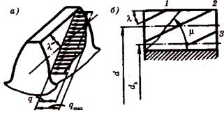
Figure 11.12 - Location of the contact line on the side surface
Forces in engagement. In a helical gear (Figure 11.13), the normal force F n broken down into three components:
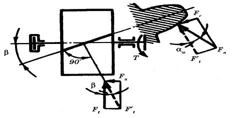
Figure 11.13 - Forces in the engagement of a helical spur gear
district force,
axial force , (11.24)
radial force ![]() .
.
Then the normal force ![]() .
.
The axial force in engagement additionally loads the shaft bearings, which is a disadvantage of helical gears.
Calculation of teeth by contact stresses. For helical gears, the specific load, taking into account formulas (11.23) and (11.24)
![]() , (11.25)
, (11.25)
where K nα is the coefficient of uneven load of simultaneously engaged pairs of teeth.
Replacing in formula (11.8) the value d w 1 per equivalent wheel diameter dvl[cm. formula (11.20)], we obtain
![]() . (11.26)
. (11.26)
Comparing the ratios in formula (1.4) for spur (formulas 11.6 and 11.8) and helical gears, we determine
 . (11.27)
Denote
 , (11.28)
Where ZHβ – coefficient of increase in the strength of helical gears in terms of contact stresses. Using formula (11.9) we obtain for helical gears
 . (11.29)
In helical gears, due to errors in cutting teeth, the two-pair engagement may be partially broken. This leads to the fact that one pair of teeth is loaded more than the other, so the coefficient K Hα takes into account load imbalance. At the same time, they distinguish K Hα for calculations on contact stresses and KFα for bending stress calculations. The values of the coefficients are selected according to recommendations from reference books, depending on the circumferential speed in the mesh and the degree of manufacturing accuracy. In the design calculation, this information is not known, so the value Z H in formula (11.29) are determined approximately. Assuming average values \u003d 12 °, \u003d 1.5 and K N α = 1, 1, we get Z nβ\u003d 0.85, and formulas (11. 10) and (11. 12) of the design calculation by multiplying numerical coefficients for helical gears will have the form
Calculate a spur gear single stage gearbox, made as a separate unit, provided that the power transmitted by the gear P 1 \u003d 10 kW, the angular speed of the gear ω 1 \u003d 78 rad / s (n 1 \u003d 750 min -1), the angular velocity of the wheel ω 2 \u003d 39 rad / s (n 1 \u003d 375 min -1). The transmission load is constant, but during the start of the gearbox, it briefly increases by 1.6 times compared to the nominal one. Transmission service life 30,000 hours.
Solution.
For transmission, we provide involute engagement without displacement. We will coordinate its main parameters with GOST 2185-66 (ST SEV 229-75). material for both gear wheels- steel 40X with bulk hardening and tempering to hardness HRC48. For transmission gears, we will take the 7th degree of accuracy according to the smoothness standards in accordance with GOST 1643-81 (ST SEV 641-77).
The gear ratio, which for a given gear is equal to the gear ratio u, according to the formula
u=2 corresponds to GOST 2185-66 and ST SEV 221-75.
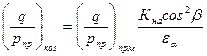
Calculate the gear teeth for contact strength and bending. From the calculation of the teeth for contact strength, we calculate the center distance of the transmission aw according to the formula 
Let's determine the values of greatness included in this formula.
We will install the transmission shafts on rolling bearings and take η=0.98. The power transmitted by the wheel, according to the formula
P 2 \u003d 9.8 kW;
torque transmitted by the wheel, according to the formula 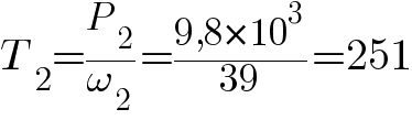
T 2 =251 N×m.
We accept the coefficient (see gear reducers) ψba =0.25. Then from the formula
 Rice. 1
From (Fig. 1) we establish that HRC48=HB460. On schedule V(Fig. 2) coefficient K Hβ ≈1; accept K Hβ =1.
 Rice. 2
Permissible contact voltage [σH] we will calculate according to the formula, having previously determined the values of the greatness included in this formula. The limit of contact endurance of the surfaces of the teeth in accordance with the table.
σ H lim b =1014 MPa.
Let's take the safety factor s H =1.1; coefficient Z R =0.95; coefficient Z v =1. The basic number of stress cycles according to the schedule (Fig. 1) for HB460 N H0 =70×10 6. Equivalent number of stress cycles according to the formula
 Rice. 3
attitude N HE /N H0 \u003d 675 * 10 6 / (70 * 10 6) \u003d 9.6 on the graph (Fig. 4) corresponds to the durability factor KHL=0.9.
 Rice. 4
Permissible contact stress according to the formula
[σ H ]=790 MPa.
Transmission center distance according to the formula 
a w =88 mm.
In accordance with GOST 2185-66 (ST SEV 229-75), we accept a w =100 mm. Dividing center distance a=a w=100 mm. Tooth module.
m=2 mm, which corresponds to GOST 9563-60 (ST SEV 310-76).
Tooth angle β=8°0′4" (cos 8°0′4"=0.99). The sum of the teeth of the gear and wheel according to the formula 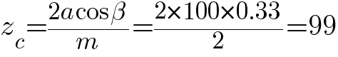
The number of gear teeth according to the formula 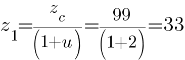
Number of wheel teeth
Let's check the formula 
the working surfaces of the teeth for contact strength according to the maximum contact stress under the action of a short-term load on the teeth. For this, according to the formula 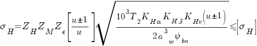
determine the calculated contact stress σ H, caused by the calculated moment T 1 and allowable maximum contact voltage [σH]max. Coefficient Z H according to the formula 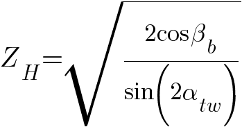
(β b =β and α tw =α/cos β)
Coefficient Z M =275 N ½ /mm. End overlap coefficient according to the formula
title=">epsilon_alpha=delim([)(1.88-3.2(1/z_1+1/Z_2))(])cos beta=delim([)(1.88-3.2(1/33+1/66 ))(])0.99=1.72">!}
Coefficient Zε according to the formula 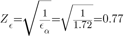
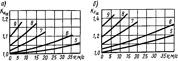
According to the graph (Fig. 5, a), the coefficient K Hα =l,05; coefficient KHβ=l(defined above) according to the table. coefficient KHv=l.
 Rice. 5
According to the formula, the calculated contact stress 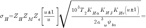
For steel 40X with bulk hardening and tempering in accordance with GOST 4543-71 yield strength σ T =700 MPa. Permissible maximum contact stress for teeth
Since the short-term transmission overload is 1.6 times more than the nominal one, then from the formula
This means that with a short-term overload, the teeth are quite strong in terms of contact endurance.
The material of the gear and wheel is the same, but the thickness of the gear teeth at the base is less than that of the teeth of the wheel, so the calculation of the teeth for bending can be performed for the gear teeth, which are less strong in bending compared to the teeth of the wheel. Let us preliminarily determine the values of the quantities included in the formula.
The torque transmitted by the gear 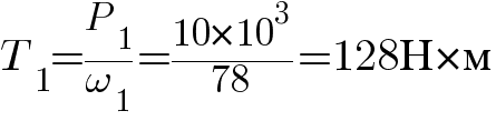
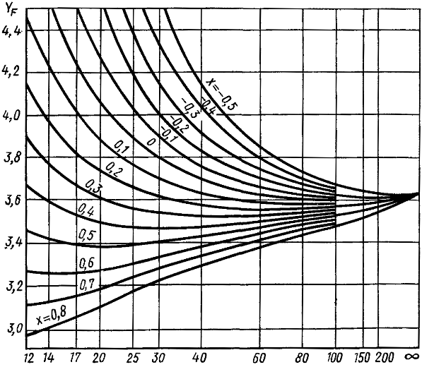
The equivalent number of gear teeth according to the formula 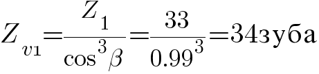
According to the graph (Fig. 6), this number of teeth corresponds to the shape factor of the gear teeth Y F =3.7. Coefficient Y ε =1. Coefficient Yβ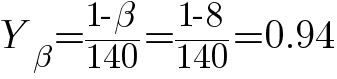
 Rice. 6
dividing d1 and initial dw1 gear diameters 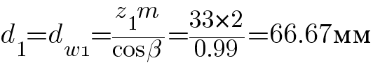
Circumferential transmission rate according to the formula 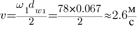
For this speed v
coefficient values K Hα And K Hv accepted correctly.
According to the graph (Fig. 5, b), the coefficient K Fa =1.05. At HB460 And ψbd =0.375 on schedule V(Fig. 2) coefficient K Fβ ≈1; accept K Fβ =1. According to the table dynamic load factor K Fv =1.02.
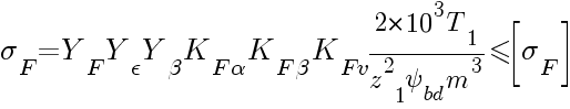
For the gear teeth, we calculate the allowable bending stress [σF] according to the formula 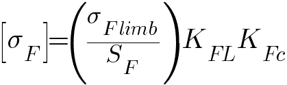
Let us preliminarily determine the values of the quantities included in this formula. According to the table bending endurance limit of teeth σ F lim b =580 MPa. Let's take the safety factor s F =1.7. Equivalent number of stress cycles N F0 =4×10 -6, the basic number of stress cycles according to
Because N FE =135×10 7 >N F0 =4×10 6, then the durability factor K EL =1. Coefficient KFc=1.
Permissible bending stress [σF] for gear teeth according to the formula
Let's make a verification calculation of the gear teeth for bending according to the formula 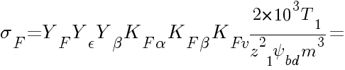
Therefore, the transmission teeth are quite strong for bending.
Let's check the teeth for plastic deformation or brittle fracture during bending under the action of a short-term overload on the teeth according to the formula. Estimated tooth bending stress caused by the design moment T1, σ F =280 MPa. Permissible maximum voltage for tooth bending
Where σ B =950 MPa- tensile strength for steel 40X with bulk hardening and tempering (GOST 4543-71). Since the short-term transmission overload is 1.6 times more than the nominal one, then according to the formula
Consequently, even with a short-term overload, the bending teeth are quite strong.
Determine the size of the teeth. In accordance with GOST 13755-81 (ST SEV 308-76), the height coefficient of the tooth heads h* a =1 and the radial clearance coefficient c*=0.25.
Height of tooth heads according to the formula 
The height of the legs of the teeth according to the formula
Formula tooth height
Pitch diameter d, vertex diameter d a and hole diameter df according to the formulas:
for gear
d 1 \u003d 66.67 mm(calculated earlier);
for wheel 
Working width ring gear according to the formula
Introduction……………..…………………………………..……………..2
1. Analysis of the kinematic scheme…………..……..………………..2
2. Kinematic calculation of the drive……………………………………3
3. Determination of the geometric parameters of a cylindrical
gear train………………………………………….…………..6
4. Geometric calculation of bevel gear………9
5. Determination of geometric dimensions and calculation for
output shaft strength……………………………………………….11
6. Verification calculation of the bearing ..……………………………….16
7. List of used literature……………………………..18
A gearbox is a mechanism consisting of gear or worm
gears enclosed in a separate closed case. Reducer
designed to reduce the number of revolutions and, accordingly, increase the torque.
Reducers are divided according to the following features:
By type of transmission - to gear, worm or gear-worm:
By the number of steps - into single-stage (when the transmission is carried out by one pair of wheels), two-, three- or multi-stage:
By type of gears - into cylindrical, bevel, or conical-cylindrical;
According to the location of the gearbox shafts in space - horizontal, vertical, inclined:
According to the features of the kinematic scheme "to deployed, coaxial. with a forked step.
1. Analysis of the kinematic scheme
Our mechanism consists of an electric machine drive (1), a clutch (2), spur gear(3), cylindrical wheels (4), bevel gear(5), bevel wheel (6), shafts (7,6,9) and three pairs of rolling bearings. Power on the driven shaft N 3 \u003d 9.2 kW, angular speed n 3 \u003d 155 rpm, the drive is designed for continuous operation, speed tolerance
5%,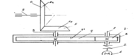
2. Kinematic calculation of the drive
2.1. Determine the overall efficiency of the drive
h=h 1 *h 2 *h 3 3 *h 4According to table 5 (1) we have
h 1 \u003d 0.93 - efficiency of a spur gear;
h 2 \u003d 0.9 - efficiency conical transfers;
h 3 \u003d 0.98 - efficiency of rolling bearings;
h 4 \u003d 0.98 - coupling efficiency
h = 0.93 * 0.98 3 * 0.9 * 0.98 = 0.77
2.2. Determine the rated power of the engine
N motor \u003d N 3 / h \u003d 11.9 kW
2.3. We select the type of engine according to table 13 (2). This is the engine
A62 with the nearest higher power value of 14 kW. This value of rated power corresponds to a speed of 1500 rpm.
2.4. Determine the gear ratio of the drive
i \u003d i nom / n 3 \u003d 1500/155 \u003d 9.78
2.5. Since our mechanism consists of a closed cylindrical gear and an open bevel gear, then we divide the gear ratio into two components:
2.6. Specify the total gear ratio
i = g.5 * 4 = 10
2.7. We determine the maximum permissible deviation of the output shaft speed
- permissible deviation of the speed according to the task.2.8. Permissible speed of the output shaft, taking into account deviations
2.9. Knowing the partial gear ratios, we determine the rotational speed of each shaft:
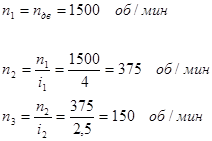
Thus, the speed of the output shaft is within the allowable range.
2.10. We determine the torques transmitted by the shafts of the mechanism, taking into account gear ratios and efficiency:
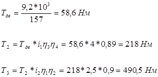
2.11 Similarly, we determine the power transmitted by the shafts
2.12. Let's build a graph of the distribution of torque and power over the drive shafts

3. Definition geometric parameters of a spur gear
3.1. For wheels with a standard initial contour, cut without offset cutting tool(x \u003d 0), it is recommended to choose the number of gear teeth in the range from 22 to 26. We choose Z 1 \u003d 22
3.2. Number of wheel teeth:
Z 2 \u003d Z 1 * i 1 \u003d 22 * 4 \u003d 88
3.3. We determine the center distance according to the formula
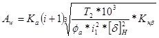
where K a - auxiliary coefficient, for helical gears is 43;
- the ratio of the width of the gear rim located symmetrically with respect to the supports, according to table 9 (3) is 0.4; - gear ratio;T 2 - torque on the low-speed shaft;
According to table 3.1 (3), we determine the steel grade for the gear - 40X. hardness > 45HRC: for a wheel - 40X. hardness
350HB.According to table 3.2 (3) for gear
The resulting value of the center distance for non-standard gears is rounded up to the nearest of a number of normal linear dimensions, A W \u003d 100 mm.
3.4. We determine the engagement modulus by the formula
where K m , - auxiliary coefficient, for helical gears is 5.8;
The resulting value of the modulus is rounded up to the standard value from the row p.59 (3). For power gears when the hardness of one of the wheels > 45HRC. modulus > 1.5 is accepted. therefore we accept the module m=2.
3.5. Determine the angle of inclination of the teeth for helical gears:
3.6. Determine the total number of gear teeth and wheels for helical gears
The resulting value is rounded down to a whole number, that is, Z = 100.
3.7. Determine the number of gear teeth
3.8. Determine the number of teeth of the wheel
Z 2 \u003d Z - Z 1 \u003d 100 - 20 \u003d= 80
3.9. Determine the actual gear ratio and check its deviation
hence the gear ratio is correct.
3.10. We define the main geometric parameters transfers and summarize them in a table
| Options | Formulas | Wheel | |
| 1 | Number of teeth | Z2 | 80 |
| 2 | Module normal, mm | m n =m | 2 |
| 3 | Pitch normal, mm | 6,28 | |
| 4 | Angle of original contour | ||
| 5 | Tooth angle | ||
| 6 | End module, mm | 2,03 | |
| 7 | Face step, mm | 2,03 | |
| 8 | Tooth head ratio | H | 1 |
| 9 | Tooth pedicle ratio | With rn > 1 | 0.25 |
| 10 | Diameter pitch circle, mm | d = Z*mt | 162.4 |
| 11 | Dividing head height, mm | h a \u003d h * m | 2 |
| 12 | The height of the dividing leg of the tooth, mm | Hf = (h + C)*m | 2,5 |
| 13 | Tooth height, mm | h = h a + h f | 4.5 |
| l4 | Lug circle diameter, mm |
d a = d + 2 h a | 166.4 |
| 15 | Cavity circle diameter, mm | d f =d - 2h f | 155,4 |
| 16 | Center distance, mm | A \u003d 0.5 (d 1 + d 2) | 100 |
| 17 | Crown width, mm | 40 |
4. Geometric calculation of bevel gear
4.1 Determine the pitch diameter of the wheel

V H is the coefficient of the type of bevel gears, for spur gears it is 1.
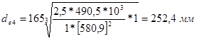
The resulting value of the external pitch diameter wheels are rounded to the nearest value from a series of normal linear dimensions in Table 13.15 (3).
d e4 = 250 mm
4.2. Determine the angles of the dividing cones of the gear and wheel

4.3. Determining the outer taper distance
4.4. Determine the width of the ring gear
4.5. Define the outer district module
where K f b - coefficient taking into account the load distribution across the width of the crown, equal to 1; (3)
V f \u003d 0.85 - coefficient of the type of conical wheels. (3)
Since the transmission is open, we increase the module value by 30%, that is, m = 5 mm.
4.6. Determine the number of teeth of the wheel and gear
4.7. Determine the actual gear ratio.
4.8. Determine the outer diameters of the gear and wheel:
dividing
;tooth tops
=109.28 mm; = 253.71 mm;tooth cavities
average pitch diameter
=85,7mm;5. Determination of geometric dimensions and calculation of the strength of the output shaft
5.1. We determine the forces acting in the engagement of the bevel spur gear:
district
radial
= 612 N, = 1530 N.5.2 Select the material for the shaft according to table 3.2 (3). This is steel 45 improved, with the following mechanical characteristics:
allowable torsional stress
5.3. Roughly determine the geometric dimensions of each stage of the shaft:
Outlet diameter
We accept d 1 = 45 mm.
Based on this, we accept the diameter under the bearing d 2 \u003d 50 mm.
5.4. We select rolling bearings in advance. According to table 7.2 (3) for bevel gear at n<1500 об/мин применяется подшипник роликовый конический однорядный. Выбираем типоразмер подшипника по величине диаметра внутреннего кольца, равного диаметру d 2 = 50мм. Это подшипник легкой широкой серии 7510: d = 50мм, D = 90мм, Т = 25 мм, угол контакта 16 0 , C r =62 kH.
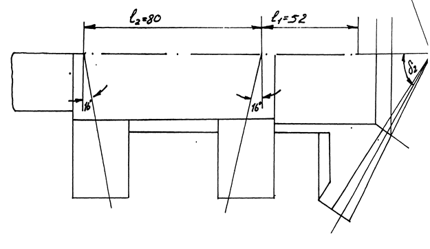
5.5. We draw the shaft steps according to the dimensions obtained in the approximate calculation and determine the distances between the points of application of the bearing reactions.
5.6. We draw a diagram of the forces in the engagement of the bevel gear.
5.7. Determine the reactions of the supports:
a) vertical plane
b) we build a diagram of bending moments in characteristic sections A, B, C (rice. 5.1)
c) horizontal plane,
Examination: ![]() \u003d 160 MPa - permissible stress value for a steel shaft.
\u003d 160 MPa - permissible stress value for a steel shaft.
The resulting value of the shaft under the bearing is rounded up to the nearest standard
As a result of the calculation, we reduce the diameter of the shaft under the wheel to 45 mm.
5.12. We expect the key to be sheared and crushed.
To fix on the shafts of the wheels, dowels are used. The dimensions of the feather keys are selected depending on the diameter of the shaft according to GOST 23360-78, b * h = 14 * 9 mm, 1 = 38 mm.
5.13. The condition of strength under deformation of the collapse is checked by the formula
where T is the torque transmitted by the shaft;
- allowable crushing stress according to Table 3.2 (3) 260 N / mm 25.14. The condition of strength under shear deformation is checked by the formula
6. Check calculation of bearings
6.1. The suitability of bearings is determined by comparing the calculated dynamic load rating with the basic one. As a result of calculations, we have: the angular velocity of the shaft
, axial force in engagement - F a= 1530 N, reactions in bearings - R XB = 3400 N, R YB = 7557 N. As a result of the calculation, we need to reduce the dimensions of the previously selected bearing, this is a light wide bearing of the 7508 series with the characteristics: d = 40mm, D = 80 mm, T = 25 mm, C r = 56 kN, e = 0.381, Y = 1.575, contact angle 14°.The bearings are installed by surprise.
6.2. Determine the axial components of the radial reactions
R g1 \u003d 0.83 e R BY \u003d 0.83 * 0.381 * 3400 \u003d 1188 H,
R g2 \u003d 0.83 e R BX \u003d 0.83 * 0.381 * 7557 \u003d 2640 H,
6.3. Determine the axial load of the bearing
R a1 \u003d R s1 \u003d 1188 N, R a2 \u003d R s1 + F a \u003d 2718 H.
6.4. We define relationships:
where V is the rotation factor. With a rotating inner ring of the bearing according to Table 9.1 (3) V = 1.
6.5. By the ratio of 0.35< 0,381 и 0,36 < 0,381 выбираем формулу для определения эквивалентной динамической нагрузки, воспринимаемой подшипником, R e ; R e = VR r K g K T ,
K g - safety factor, according to Table 9.4 (3) K g \u003d 1.2,
K T - temperature coefficient, according to the table. 9.5 (3)=1, K T then
R e \u003d 1 * 3400 * 1.2 * 1 \u003d 4080 H,
6.6. Determine the dynamic load capacity
where L h is the required bearing life, during long-term operation of the drive, we take 5000 hours.
C rp< С r , значит подшипник пригоден к применению.