The rules for making drawings of cylindrical worms and worm wheels are regulated by GOST 2.406-76.
5.1 Rules for making working drawings of worms
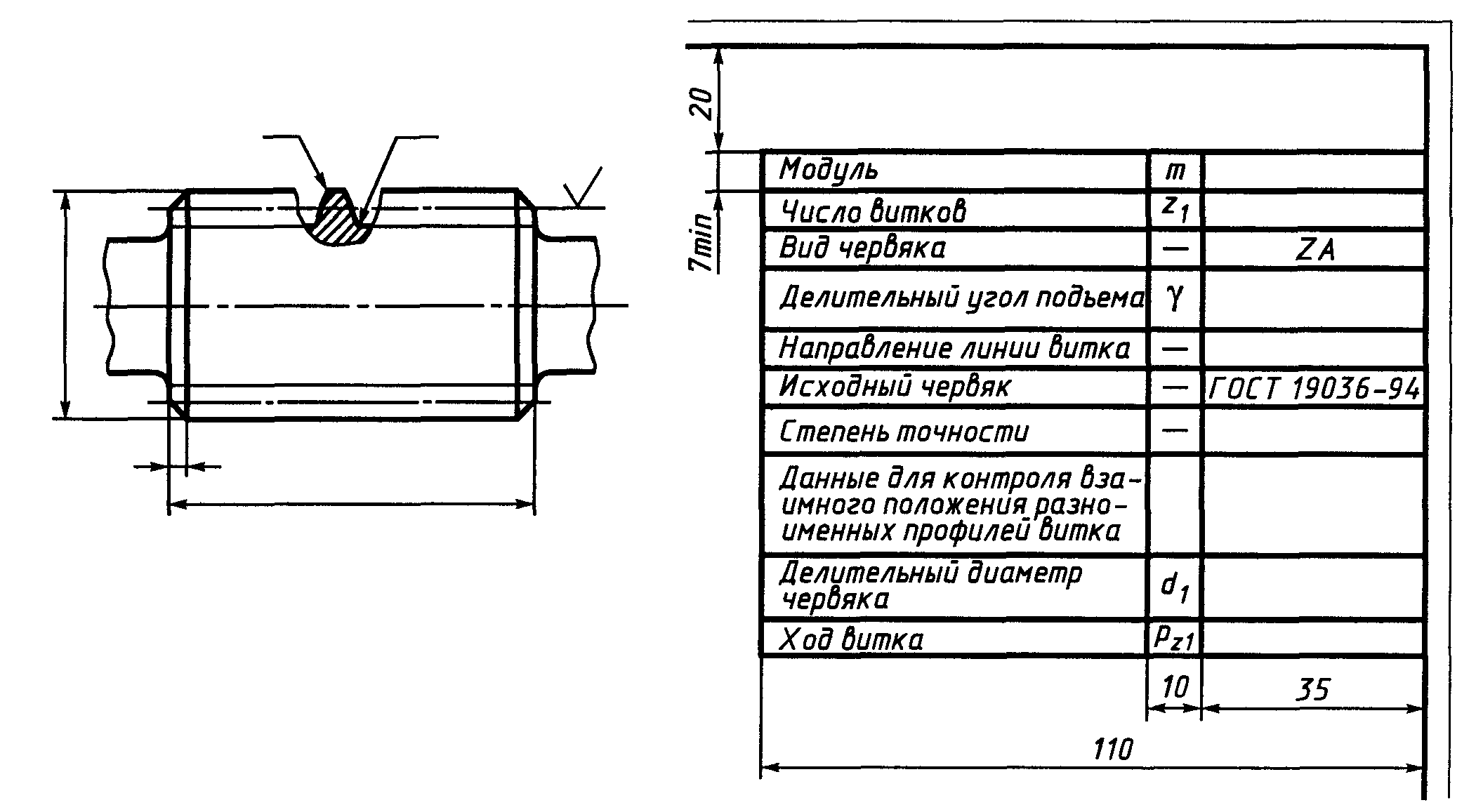
The image of a cylindrical worm (Fig. 15) should indicate:
coil top diameter d A 1 ;
length of the cut part of the worm b 1 ;
data defining the contour of the cut part of the worm, for example, linear or angular dimensions of the chamfer, etc.;
radius of curvature of the transition curve r f 1 ;
radius of curvature of the coil blunting line r k 1 or chamfer dimensions;
roughness of the side surfaces of the coil.
The drawing of the worm should contain a table of parameters consisting of three parts, which should be separated from each other by solid main lines:
IN first part tables of worm gear parameters should be given (Fig. 15):
module T;
number of turns z 1 ;
type of worm - entry by type: ZA, ZI, etc.;
helix angle:
basic g V- for a worm of type ZI;
divisive g- for other types of worms;
the direction of the coil line is indicated by the inscription “Right” or “Left”;
source worm: for a standard worm - by reference to the corresponding standard;
In second part Tables of worm gear parameters must contain data for monitoring the relative position of opposite coil profiles according to one of the following options:
pitch thickness along the chord of the turn and height to the chord  ;
;
worm size by rollers M 1 and measuring roller diameter D.
IN third part tables of worm ring parameters should be given:
worm pitch diameter d 1 ;
turn stroke r z 1 ,
if necessary, other reference data, for example:
center distance A w ;
worm diameter coefficient q;
worm helix height h 1 ;
number of teeth of the mating worm wheel z 2 ;
worm main diameter d V - for a worm of type ZI;
designation of the drawing of the mating wheel.
|
|
|
Rice. 15. An example of specifying the parameters of a ring gear in a drawing worm species ZA (Archimedean worm) |
5.2 Rules for making working drawings of worm wheels
The image of the worm wheel (Fig. 16) should indicate:
tooth tip diameter d a 2 ;
largest diameter d a M 2 ;
crown width b 2 ;
data defining the contour of the wheel crown, for example, chamfer dimensions or the radius of rounding of the end edges of the teeth, the radius of the recessed surface of the tips of the wheel teeth, etc.;
the distance from the base end to the middle end plane of the wheel and, if necessary, to the center of the recess of the surface of the tops of the wheel teeth;
radius of curvature of tooth transition r f 2 ;
radius of curvature of the tooth blunting line r k 2, or chamfer dimensions;
roughness of the side surfaces of the teeth.
The wheel drawing should contain a table of parameters consisting of three parts, which should be separated from each other by solid main lines:
the first part is basic data;
the second part is data for control;
the third part is reference data.
IN first part Tables of parameters of the worm wheel ring gear should be given (Fig. 16):
module T;
number of teeth z 2 ; for a gear sector, the number of teeth of the sector gear should be indicated;
the direction of the tooth line is indicated by the inscription “Right” or “Left”;
worm displacement coefficient X;
original production worm: for a standard worm - by reference to the corresponding standard;
degree of accuracy and type of mating according to the lateral clearance standards according to the relevant standard and the designation of this standard.
Part two the tables of rim parameters on the worm wheel drawing are not filled out.
IN third part The tables of the rim parameters on the drawing of the worm wheel should be given:
center distance A w ;
pitch diameter of worm wheel d 2 ;
number of sector teeth;
type of conjugated worm;
number of turns of the mating worm z 1 ;
designation of the drawing of the mating worm;
if necessary - other reference data, for example, center-to-center distance in processing a 0, etc.
Unused parameter table rows should be deleted or crossed out.
References
GOST 2.406-76. Rules for making drawings of cylindrical worms and worm wheels. M.: Standards Publishing House, 1998.
GOST 3675-81. Basic norms of interchangeability. Cylindrical worm gears. Tolerances.
GOST 18498-89. Worm gears. Terms, definitions and designations.
GOST 19036-94. Cylindrical worm gears. The original worm and the original producing worm.
GOST 19650-97. Cylindrical worm gears. Calculation of geometric parameters.
GOST R 50891-96. Gearboxes for general machine-building applications. General technical conditions. M.: Publishing house of standards, 1996. – 27 p.
Dunaev P.F., Lelikov O.P. Design of machine components and parts: Tutorial for technical specialties of universities. M.: Higher School, 2001. – 447 p.
Reshetov D.N. Machine parts - M.: Mechanical Engineering, 1989 - 496 p.
Sheinblit A.E. Course design of machine parts. Textbook – Kaliningrad: Amber Tale, 2004 – 454 p.
Shelofast V.V. Fundamentals of machine design - M.: APM Publishing House, 2000 - 472 p.
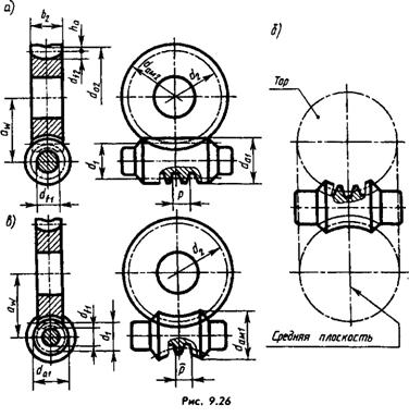
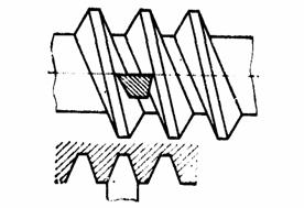
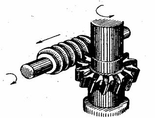
A worm gear consists of a worm wheel and a worm. The latter is a screw with one or several turns (entrances), for example three (Fig. 9.25), of a certain profile.
There are gears with a cylindrical worm - the dividing surfaces of the worm and the wheel are cylindrical (Fig. 9.26, a) and globoid - the dividing surface of the worm is part of the surface of the torus (Fig. 9.26,6), and of the wheel - cylindrical (Fig. 9.26, c) .
Note. In the drawings, the designations are given as if for disconnected wheels and worms. Therefore, for the convenience of their further use, the subscripts “w” are omitted.
The lateral surfaces of the turns can be ruled (helical) and non-linear.
The three most widely used types of cylindrical ruler worms are Archimedean (ZA), involute (ZI) and convolute (ZN).
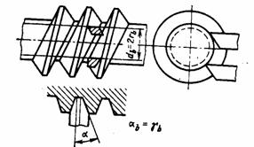
Archimedes' worm side surfaces screw turns are limited by Archimedean helicoids, their end sections (end profile) are by Archimedes spirals (see Fig. 9.25). During their manufacture, the direction of the straight cutting edge of the cutter, forming the surface, intersects the geometric axis of the worm at a certain constant angle.
In an involute worm, similar surfaces are limited by involute (unfolding) helicoids. Their end sections are involutes of a circle (see Fig. 9.25). The directions of the cutting edges of the cutters are tangent to the helical lines of the worm.
The convolute worm has similar surfaces - convolute helicoids. Their end sections are elongated or shortened involutes (see Fig. 8.10). The directions of the cutting edges of the cutters are tangent to cylindrical surfaces, the axes of which coincide with the axis of the worm.
The axial cross-section of the turns of these worms is an isosceles trapezoid with an angle of 40°. In uncorrected worm gears aw=0.5(d1+d2), the heights of the wheel tooth head and the worm turn are equal to the module m=p/pi (see Fig. 9.26), the legs are 1.2m.
Wheel pitch diameter d2, as with uncorrected cylindrical and conical gears, is equal to mz2.
Therefore, the diameter of the tooth tip circle
da2 = d2 + 2m = m (z2+2), depressions - df2=m(z2-2.4).
Screw pitch diameter d1=mq, where q is the worm coefficient, the values of which are given in GOST 2144-76*. The diameter of the tops of the worm turns is da1=d1+2m=m(q+2), the diameter of the bottoms is df1=m(q-2.4)=d1-2.4m.
Instead of the number of teeth on the worm, indicate the number of turns z1 (entries) equal to 1...4. The transmission parameters include the turn stroke - p21=pz1=pi*m*z1 and the pitch angle of the turn line?=p/pi*d1.
On working drawings of worms and wheels, some of the parameters are placed in images, some - in tables similar
indicated in Fig. 9.13 and 9.21. For their full content, see GOST 2.406-76* for cylindrical worms and wheels and GOST 2.407-75 for globoid ones.

On training drawings some columns of the tables are left blank or excluded (Fig. 9.27 and 9.28). When drawing up a drawing (sketch, see; in paragraph 10.1) from life, measure da as accurately as possible (for wheels and globoid worms in the middle section), the height of the coil or tooth and, taking h = 2.2m, calculate the module. The obtained values are checked with standard modules (see p. 291) and if there is a discrepancy, the closest one is accepted, which is used in further calculations. Measure p, calculate z1 and z2.
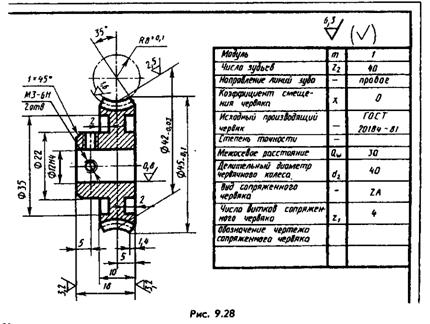
The pitch diameter of the worm is determined from the formula d1=da1-2m. Knowing d1 and m, you can determine the q-coefficient of the worm diameter, which can be used to refine the calculations, since it can have values of 8; 9; 10; 11.2; 12.5; 14; 16; 18; 20; 25 (GOST 2144-76*).
The helix angle is calculated using the formula (accurate to minutes) or determined by measuring it on a scan of the surface of a cylindrical worm, which is easy to obtain by wrapping the worm in a sheet of paper and imprinting helical lines on it.
If the drawings of the worm and wheel are performed when detailing the drawing general view, then it must contain the appropriate parameters. In their absence, the parameters are determined by measuring the corresponding image elements.
The image of the worms must be done as shown in Fig. 9.27 and 9.29.
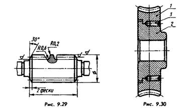
The roughness of the side surfaces of the teeth and turns is applied on the lines of the pitch surfaces.
Worms and wheels are made from steel (for example, steel 45, 40X, etc.), bronze (for example, BrOTsO5-3-5) and polymers. To save expensive bronze, it is used to make only ring gear, strengthened in one way or another on a hub made of cast iron or cheap steel (Fig. 9.30). Such drawings are prepared as assembly drawings.
In cylindrical worm gears, the following types of worms are most common (GOST 18498 - 73): Archimedean (ZA), involute (ZI) , convolute with straight coil profiles (ZN 1), convolute with rectilinear cavity profiles (ZN 2), convolute with a straight normal coil profile (ZN 3) and formed by a cone (ZK 1) and (ZK 2).
IN recent years Transmissions with worms are used, the turns of which in the normal section have profiles in the shape of a circular arc - cylindrical worms formed by a torus (ZT 1).
The geometry of each of these types of worms is associated with its own technological methods.
Depending on the scale of production and hardness, cutting of turns of cylindrical worms can be done in various ways. In single and small-scale production, worms that are not subjected to heat treatment or heat-treated to a hardness of HR C e 38 are cut with profile cutters, disk or finger cutters, and in serial and mass production - by a vortex method or plastic deformation. For worms hardened to a hardness of HR C e 51 or more, the finishing operation for processing the working surfaces of the turns is grinding.
Home technological feature The geometry of cylindrical worm gears, which distinguishes them from other types of gears, is that the producing surfaces (producing worm) of the tool when cutting the teeth of a worm wheel using the rolling method must coincide or in a certain way slightly differ from the working surfaces of the worm itself. As such a tool, hob cutters are usually used, which are a cylindrical worm, the turns of which are intersected by helical grooves to form cutting edges, and the side surfaces and surfaces of the apexes have backs to form rear cutting angles. The cutting edges of the cutter must lie on the imaginary surface of the worm of the required type.
The worms and worm wheels themselves, before the formation of the gearing elements, are bodies of rotation and conventional processing methods are used in their manufacture.
Processing of threads of cylindrical worms
Cutting cylindrical worms with profile cutters
on lathes
Archimedes worm Z A has a rectilinear coil profile in the axial section AA (Fig. 3.4) and a curved profile in the normal section. The end section of the coil is an Archimedean spiral. Involute worm Z 1 has a rectilinear coil profile in a section with a plane tangent to the main cylinder, and a curved profile in a normal section; the end section is an involute. Coil of convolution worm ZN 1 has a rectilinear profile in the explosive section , perpendicular to the coil, worm coil ZN 2 - in the BB section , perpendicular to the cavity, and the turn of the worm ZN 3 - in sections of GG , perpendicular to the lines of the coil. All convolute worms have a curved coil profile in the axial section AA, and an elongated or shortened involute in the end section.
Rice. 3.4. Sections of cylindrical worms: AA - axial, BB - section normal to the cavity; BB - section, normal turn; GG - section normal to the coil lines
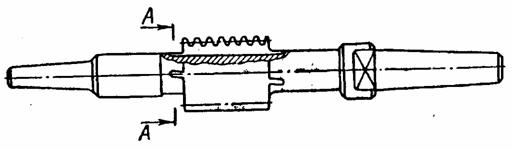
Worms are the most technologically advanced Z A, the processing of which is lathe practically no different from processing screws with trapezoidal threads. The cutter is installed so that its cutting edges lie in the axial plane of the worm. The installation of a double-sided cutter with a straight profile is shown in Fig. 3.5. This method of cutting a helix can only be recommended for worms with a small helix angle due to the difference in cutting conditions on the left and right sides. For finishing cutting of worms Z And with an elevation angle of the coil line up to 10° It is recommended to separate the left and right sides of the coil with single-sided cutters.
The installation of single-sided cutters is shown in Fig. 3.6. When cutting worm turns with a one-sided cutter, it is possible to alternately process both sides of the cavity with one cutter by turning the worm.
|
|
|
|
|
Rice. 3.5.Diagram for installing a double-sided cutter when cutting a wormZ A |
Rice. 3.6.Scheme for installing one-sided cutters when cutting a wormZ A |

The cutter installation diagram for cutting worms of type ZN 1 and ZN 2 is shown in Fig. 3.7, 3.8.
Convolute worms (ZN 1 and ZN 2) are cleanly cut with one or two cutters with straight cutting edges, located for the ZN 1 worm (Fig. 3.7) in the normal section of the turn and for the ZN 2 worm (Fig. 3.8) in the normal section of the cavity. The angles of the turn profile a nT and in the normal section of the cavity nS according to GOST 19036 - 73 are assumed to be the same, equal to 20°.
The installation of the cutter for cutting a ZN 3 worm coil with a straight profile in a section normal to the profile is the same as for cutting the ZN 2 worm coils.
When cutting an involute worm ZI, cutters having a rectilinear profile are installed so that the horizontal plane passing through the cutting edge is tangent to the main cylinder. The installation of cutters when cutting involute worms is shown in
rice. 3.9, 3.10.
|
|
|
|
|
Rice. 3.9. Installation diagram of cutters for cutting the right wormZI |
Rice. 3.10. Installation diagram of cutters for cutting the left worm ZI |

Cutting cylindrical worms using milling method
Milling is carried out on thread milling, gear hobbing or special machines for milling worms. Disc or finger cutters are used as tools. Milling is a more productive operation than cutting with cutters.
Disc cutters for preliminary cutting of all types of worms are made with a trapezoidal profile. For finishing milling or for grinding turns, each standard size of worm must correspond to a special cutter with curved cutting edges.
Cutting worms with disc cutters is mainly used for rough milling of worm turns, worms no more precise than the 9th degree of accuracy.
In the case of using disk cutters with straight cutting edges and the location of the cutter axis at an angle g (Fig. 3.11) to the worm axis, only ZK 1 type worms, in which the generatrices of the helical surfaces are not straight lines, can be completely milled.
To facilitate the production of ZI and ZN worms, it is allowed to use cutters with a straight profile, provided that the resulting error in the worm profile is less than the tolerance left for finishing.
The milling method is used to pre-process worm turns with concave profiles of the type ZT 1 (cylindrical worms formed by a torus, the axis of which intersects with the axis of the producing torus at an angle equal to the dividing angle of elevation of the worm turn), ZT 2 (cylindrical worms formed by a torus, the axis of which intersects with the axis generating torus at an angle at which one of the flat sections of the main surface of the worm is an arc of a circle coinciding with the generatrix of the generating torus) . The tool used is a disk cutter with a mountain-shaped surface.
Finger cutters are used for milling turns of large worms when it is not possible to use any other tool.
Gearing with rolling cutters (vortex cutting of turns)
This method consists of cutting worms by turning with continuous rolling. The tool used is a straight or helical involute cutting wheel (resembling a gear cutter). There is a forced kinematic connection between the rotation of the worm and the cutter. Feed during cutting occurs due to the axial movement of the worm workpiece (or a support with a cutter) with synchronous additional rotation of the cutter (Fig. 3.12). Cutting worms using the gear turning method can be done on special machines (model EZ-10A) or gear hobbing machines with a tangential feed feed. Depending on the geometry and sharpening of the cutter, as well as on relative position worm and cutter, worms with different geometries can be processed (Archimedian, convolute, involute).
|
|
Rice. 3.12. Cutting a worm using the tooth turning method |
For worms subjected to heat treatment, cutting is a preliminary operation performed with an allowance for grinding.
Rolling turns of the worm.
Rolling is the most productive and least material-intensive processing method. Rolling is carried out on roller rolling machines (mills). Worms cm< 3 мм накатывают на двухроликовых станках в холодном состоянии, а приm ³ 3 мм – на трехроликовых станках, нагревая заготовку обычно с помощью ТВЧ. Принципиальная схема накатных станков показана на рис.3.13.
|
|
|
|
|
Rice. 3.13. Schematic diagrams machines for rolling worms: A) - three-roll; b) - two-roll; 1 - blank; 2 - movable roller; 3 - supporting knife; 4 - stationary roller |
||
Deviations in dimensions (mm) of screw surfaces of worms obtained by cold rolling (m = 1...2 mm) are as follows:
By step………………………………………………………………………………….0.015
According to the thickness of the tooth pitch diameter………………………….0,02 - 0,03
According to the radial runout of the worm coil relative to the axis of the centers...0.1 - 0.25
According to fluctuations in the diameter of the depressions……………………………………………..0.05
If the center holes are processed after rolling, basing the workpiece on working profiles, then the radial runout can be reduced to 0.04 - 0.08 mm. Thus, by cold rolling it is possible to obtain worms corresponding to 8th degree of accuracy, and according to individual parameters- 7th degree of accuracy.
The deviations in dimensions (mm) of the helical surfaces of worms obtained by hot rolling are as follows:
By step………………………………………………………………………………… 0.03 - 0.05
According to the thickness of the tooth at the pitch diameter…………………………. 0.03 - 0.05
According to the radial runout of the worm turn relative to the axis of the centers....0.3 - 0.8
According to fluctuations in the diameter of the vertices, no more than…………………...0.4
According to fluctuations in the diameter of the depressions at m< 5 мм, не более……………………0,1
Grinding the side surfaces of the worm turns
Grinding of turns of Archimedean, involute and convolute worms is usually done disk circles with curvilinear generatrices cutting part, obtained by editing circles special device. In this case, the axis of the circle makes an angle g with the axis of the grinding worm (Fig. 14).
For cylindrical worms ZA, only worms of the 8-9th degree of accuracy can be grinded with a disc wheel with a straight generatrix due to significant distortions of the profile.
A feature of the geometry of involute worms is the possibility of grinding their turns with circles with straight generatrices of conical surfaces coinciding with the generatrices of the helical surface of the involute worm (Fig. 3.15). With this grinding scheme, the axis of the wheel is parallel to the axis of the worm.
In Fig. Figure 3.16 shows a diagram of grinding an involute worm forming the cone of a cup wheel. Each side of the coil is ground separately when installing the wheel. When grinding the turns of an involute worm using the end plane of a wheel, each side of the turn is ground separately. The end plane of the wheel with this grinding scheme must lie in the plane, which represents the side of the tooth of an imaginary rack that engages with the involute screw.
In Fig. Figure 3.17 shows a diagram of grinding an Archimedean worm with a cup-cone wheel. Grinding with a cup cone wheel with a straight cone generatrix makes it possible to ensure profile accuracy within the 8th - 9th degree of accuracy.
When grinding with a cup wheel with a straight generatrix of the conical part of the wheel, the profile of the coil is closer to an Archimedean spiral than when grinding with a disk wheel. To obtain an accurate profile of the grinding worm, the grinding wheel must be dressed along a curve.
Large-module Archimedean and convolute worms (m > 25) are ground with finger profile wheels, which ensures the 8-9th degree of accuracy (Fig. 3.18).
Allowance amount for grinding the side surfaces of the turns is given intable 3.1. Large allowances according to the table are prescribed for less rigidworms, as well as in cases where significant deterioration is possibleformations during mechanical or heat treatment: for worms, I havecutting grooves for tool exit; for worms, side surfacesturns of which are obtained by plastic deformation methods; for blackvyakov with increased distances between bearings or exposedrepeated heat treatment, etc.
Table 3.1
The amount of allowance for grinding the side surfaces of turns of cylindrical worms (per side), mm
|
m, mm |
Diameter of projectionsd a 1 , mm |
||||
In the manufacture of precision worms, after preliminary cutting, before carburizing and hardening, the first grinding of the turns is carried out, which ensures a minimum and uniform allowance for subsequent operations. After heat treatment, several grinding operations are performed with intermediate restoration of the technological bases and removal of residual stresses by keeping the worm for several hours in a heated oil bath. Final grinding is carried out under constant temperature conditions using precision equipment.
Lapping and polishing the worm
To reduce the surface roughness of the coils, the worms are ground in and polished. Lapping is carried out on special or universal lathes. A cast iron or textolite worm wheel is used as a lap, mounted on an axis fixed in the machine support and engaged with a rotating worm. To process turns along the entire length of the worm, the caliper must perform a reciprocating movement along the worm. The lapping is slightly slowed down by a special device, and an abrasive mixture is supplied to the engagement zone, which includes: electrocorundum with a grain size of 5 - 32 (4%), crocus (4%), paraffin (2%) and machine oil (90%). Metal removal during grinding should not exceed 0.01 - 0.02 mm. Processing time 2 - 5 minutes. The lapping process should not be used to correct errors in the profile and pitch of worms.
The worm turns of heavily loaded gears are polished to achieve a minimum unevenness height. Polishing is carried out with a rapidly rotating felt or felt wheel coated with polishing paste. The felt circle is forced to move along the helical groove of a slowly rotating worm. Final polishing is carried out using a cloth wheel with polishing paste.
Cutting worm gear teeth
The processing of worm wheels before the gear cutting operation does not have any fundamental specificity compared to the processing of conventional round parts of a similar class.
Two methods are used for cutting the teeth of worm wheels on gear hobbing machines:
1) hob cutters with radial or axial tool feed;
2) flying cutters or multi-tooth cutters with axial feed.
In both methods, the cutting edges of the tool must reproduce in space the surface of the producing worm, which is in engagement with the worm wheel being cut at the same center-to-center distance as with the working worm.
The difference between a nominal tool producing worm and a working one is the increase (by double the radial clearance) in the diameter of the vertices and the guaranteed lateral clearance of the thickness of the turns. In addition, the tool worm must have rounded turns to form transitional curves at the base of the teeth of the worm wheel being cut.
Cutting the teeth of worm wheels with hobs
When cutting wheels with hobs, the axial feed method is preferable, since the radial feed method does not ensure complete processing of the tooth surfaces and at the same time can lead to excessive cutting of sections of the working surfaces of the latter. With radial feed, the side surfaces of the teeth usually acquire a cut with the number of edges equal to the number cutting teeth of the cutter at the length of the normal pitch of the worm.
In a transmission with worm wheels cut by radial feed, it is almost impossible to ensure the required accuracy according to contact standards. Such gears require long-term running-in, are not able to bear the rated load, and are prone to jamming.
Cutting is carried out with a milling cutter while gradually reducing the machine center distance between the tool and the workpiece. The method isthe most productive compared to others and is used both in mass and serial production (in single production, cutting is done with a cutter), ensures cutting of wheels of the 8th degree of accuracy. When cutting wheels with multi-turn cutters, it is necessary that the number of teeth of the wheel being cut and the number of turns of the cutter do not have common factors, and also that the number of grooves of the cutter is not a multiple of the number of turns.
Cutting is performed at a constant center distance, and the tool feed movement is carried out by moving it along the axis. With this feeding method, greater profile accuracy is achieved than with the radial one; it depends only on the feed amount.
Appearance hob cutter for working using the radial feed method is shown in Fig. 3.19 A, and for working using the home-machine feeding method - in Fig. 3.19 b.
With axial feed of cutters, which also have a small number of cutting teeth along the normal pitch length, the cutting of the side surfaces of the wheel teeth depends on the axial feed of the cutter per revolution of the wheel and is usually practically not noticeable.
|
A) |
|
|
|
|
||
|
Rice. 3.19. Hob cutter for cutting worm wheels |
||

To unload the cutting teeth, which, during axial feed, are the first to cut into the wheel, the intake part of the cutter is made conical (Fig. 3.19 b). The intake part is followed by a cylindrical section, the teeth of which form the surface of the wheel teeth. Cutters with a fence cone have increased resistance and durability. To increase the durability of finishing tools in mass production, wheels are pre-cut using milling cutters with thinned turns using the radial feed method and finishing with milling cutters with axial feed.
Cutting worm wheel teeth with cutters
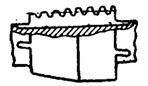
In the manufacture of especially large worm gears, as well as in individual and small-scale production, when there is no practicality in manufacturing hob cutters for cutting worm wheels, flying cutters (Fig. 3.20) or, for multi-start worms, cutting heads (Fig. 3.21) can be used. In this case, to completely form the lateral surfaces of the teeth, you can use only the axial feed of the tool with its movement from the beginning to the complete end of cutting. Therefore, it is necessary to have such a length of the mandrel in which the cutter is installed to ensure the required length of pulling of the cutter. The shape and position of the cutting edges of the cutters must correspond to the position and shape of the generatrices of the helical surface of the worm that engages with the wheel being cut.
Thus, with Archimedean worms (ZA), the cutting edges of the cutter are located in the axial plane of the cutter mandrel, with convolute worms in the plane normal to the turn or cavity.
Worm wheels of large modules are sequentially processed by several cutters (Fig. 3.22).
Shearing of worm wheel teeth
Shearing the teeth of worm wheels is a finishing operation and is used for wheels of the 6th degree of accuracy and more accurate. Shewing is carried out after finishing milling.
A worm gear is a worm whose surface geometry completely coincides with the geometry of the working worm’s turns. Cutting properties Shever acquires at the expense of large number small radial grooves present on the surface of the coils.
Shearing can be performed in two ways: radial feed movement with backlash-free engagement (approaching to the nominal center distance) and circumferential feed movement. In both cases, the wheel rotates by rotating the shaver cutter (the table drive mechanism does not work).
When shaving using the radial feed movement method, the shaver must have a coil thickness equal to the width of the wheel cavity. When moving the wheel using the circular feed motion, the tooth of the shaver must engage with the wheel with a gap if the nominal center distance is set. Shaving of the profile occurs due to the fact that the shaver cutter leads (rotates) the wheel blank, which in some cases is braked. After processing one side, the direction of rotation of the shaver changes and shaving is performed by the other part of the shaver, which has the opposite direction of the teeth (notches).