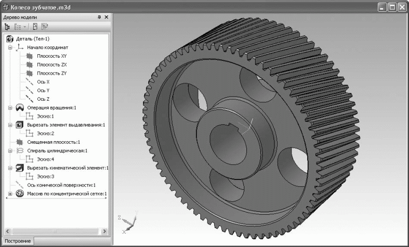
As in the previous work, to start the calculation, you need to start the system, create a new drawing, open the "Library Manager" menu, then open the "Calculation and Construction" folder and launch the "KOMPAS SHAFT 2D" application (Figure 2.5). In the running application, create a new model and select the rendering type (Fig. 2.6).
If the gear design has a symmetrical arrangement ring gear(rim) relative to the hub, and the length of the hub is equal in length to the width of the rim of the gear wheel (rim), then the construction of the model is greatly simplified and you can start building immediately from the gear rim. If the ring gear (rim) is located asymmetrically relative to the hub or the length of the hub is greater than the width of the gear ring, then construction must begin in the same way as in the previous work - from the construction of the hub.
Consider the first case (the ring gear is located symmetrically with respect to the hub, the length of the hub and the width of the rim are equal). In the window of the program "KOMPAS SHAFT 2D" (Fig. 2.6) it is necessary to activate the icon "Elements mechanical gears". In the menu that appears (Fig. 2.5), select the spur gear.
In the appeared menu of the program for calculating mechanical gears "GEARS" (Fig. 2.6), select the type of gear with the mouse cursor (in this work, external gearing) and activate the icon.
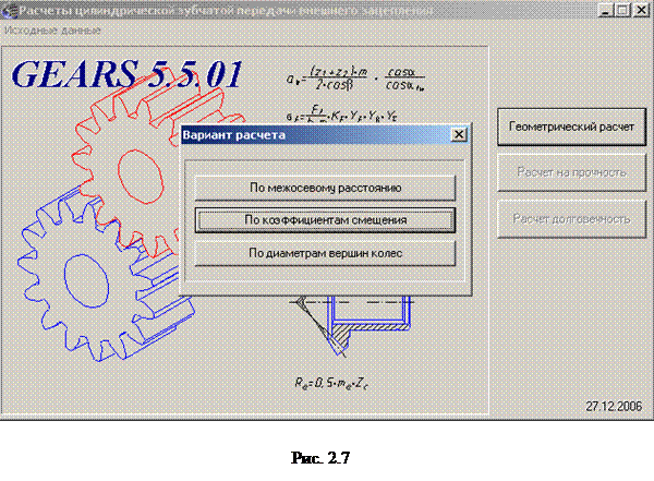
In the appeared window of the program "GEARS 5.1.01" (Fig. 2.7) activate the icon ![]() , in the "Calculation option" menu that appears, select calculation by center distance. The “Geometric calculation” menu will appear on the screen (Fig. 2.8), in which it is necessary to enter the engagement parameters obtained during the calculation in paragraph 3.3. It is also necessary to pay attention that geometric calculation presented on two pages, to go to the next page, you need to activate the icon with the mouse cursor. On the second page, one of the input parameters is the offset coefficient; in this paper, the tool offset coefficients are taken equal to zero.
, in the "Calculation option" menu that appears, select calculation by center distance. The “Geometric calculation” menu will appear on the screen (Fig. 2.8), in which it is necessary to enter the engagement parameters obtained during the calculation in paragraph 3.3. It is also necessary to pay attention that geometric calculation presented on two pages, to go to the next page, you need to activate the icon with the mouse cursor. On the second page, one of the input parameters is the offset coefficient; in this paper, the tool offset coefficients are taken equal to zero.
After entering the transmission parameters, a calculation should be made by activating the “Calculation” icon with the mouse cursor.
 |
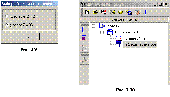
If all the initial data for the calculation are entered and are correct, then the following inscription will appear in the lower part of the geometric calculation menu window: “Controlled measurement parameters and quality parameters are normal” (Fig. 2.12). In the "Select construction object" window, select "Wheel" (Fig. 2.9). In the menu (Fig. 2.6) enter the dimensions of the chamfers and activate the dimensioning option. To complete the formation of the gear rim, click the icon with the mouse cursor.
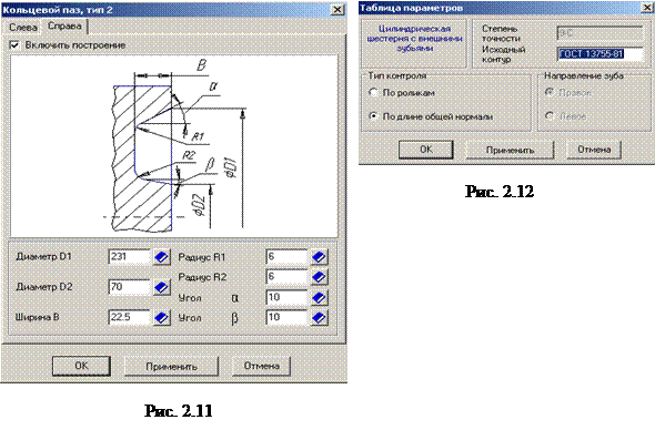
In order to build the design of the gear shown in Fig. 2.3, it is necessary to activate the icon "Additional elements of steps" with the mouse cursor in the menu of the program "KOMPAS SHAFT 2D" (Fig. 2.6) and select the icon "Annular grooves" (Fig. 2.10). The type and design parameters of the annular grooves depend on the type of gear blank, since the analysis of the choice of the blank is not included in this work. Any type of annular grooves can be chosen, for example "Type 2".
In the window that appears (Fig. 2.11), you must set the parameters of the annular grooves on the left and right according to the calculations carried out in paragraph 2.5. By activating the icon again with the mouse cursor, you can generate a table of parameters for the gear being designed (Fig. 2.12).
The inner contour of the gear wheel model (a hole with a keyway in the hub) is built in the same way as in the previous work (section 2.6).
![]()
 |
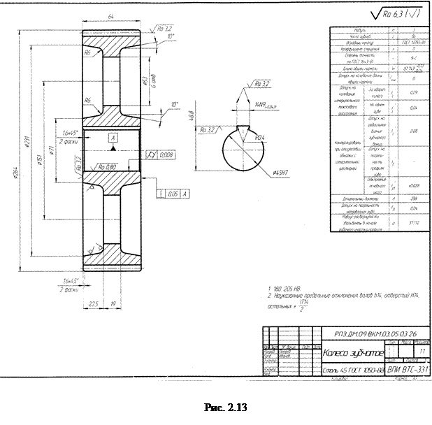
The final working drawing of the gear wheel is reduced to the form shown in Fig. 2.13. On the drawing of the model built in "KOMPAS SHAFT 2D", the table of parameters is shown in full. If necessary, using the editing tools, the parameter table can be brought to the form shown in Fig. 2.4. The radial run-out tolerance of the ring gear is given in the design table and is therefore not specified separately in the drawing.
2.10. Control questions for the design assignment
1. Basic geometric parameters of a spur gear?
2. What is the performance criterion for calculating the center distance?
3. How does the change in the angle of inclination of the teeth affect the operation of the gear and its dimensions b?
4. Is there a relationship between the engagement modulus and the pitch diameter?
5. What is the relationship between the circumferential (end) and normal module?
7. Which module, normal or district, is the standard for helical gear and why?
8. How are the diameters of the tops and bottoms of spur gears determined?
9. What forces arise in helical gearing?
10. What determines the value of the tooth shape factor for spur and helical gears?
11. What parameter determines the degree of gear accuracy?
12. How to determine the design load factor?
13. Does the tooth strength in bending calculation depend on the engagement modulus?
14. What are the most common gear materials?
15. Which of the gears (gear or wheel) is used to calculate the teeth for contact strength?
16. What are the main structural elements consists of a gear wheel?
17. What are the holes in the gear disk for?
18. What types of calculations can be carried out for a spur gear using the KOMPAS-3D program?
19. What steps need to be taken to create chamfers on the outer and inner diameters of the hub?
20. How to build annular grooves on a gear wheel model using the application to the KOMPAS-3D program?
21. What basic information should be contained in the parameter table for a spur gear?
Since our example is educational, some simplifications will be made when modeling a gear wheel. In particular, instead of the involute forming the tooth profile, we will build ordinary arcs, bringing them as close as possible to the involute and trying not to disturb the engagement. This is due to the fact that it is not so easy to build an involute manually, in addition, accurately modeled involute teeth are rebuilt for a very long time. However, you should not worry - the model itself will not suffer from this at all.
Create a new document KOMPAS-Detal, save it under the name Cogwheel.m3d in the directory reserved for the gearbox files. Set the orientation of the part to Isometric XYZ (using the drop-down menu of the Orientation button on the Standard toolbar). In principle, it is not necessary to do so. I, for one, am more used to it. You can choose not to set this isometric. However, keep in mind that you will use orthogonal planes other than those given in the examples as reference planes. In all models of the gearbox considered in the example, this orientation is set.
AT in general terms the order of construction of the wheel is as follows: first, you need to model the blank of the wheel using the rotation operation, then cut the keyway and holes in the disks, and lastly, form the ring gear.
So let's get started.
1. Select a plane in the construction tree XY and click the Sketch button. Construct in the sketch the contour of the half section of the gear. You can draw it as described in Chap. 2 (the main thing is that it has exact dimensions), but it is much easier to copy this outline from the gearbox drawing (from the top view). Remember that the sketch outline must not contain any breaks or intersect itself. In addition, the sketch must have one axis - a horizontal segment, made with the Axial style and passing through the point of origin of the sketch (Fig. 3.53).
Rice. 3.53. Sketch of a basic wheel spin operation
Please note that all chamfers and fillets that should be on the wheel are already drawn in the sketch at the corners of the contour. This way you avoid having to create these 3D elements with separate operations in the model.
Note
The gearbox model is not parameterized to keep the example simple, so sketch parameterization can be turned off during construction.
2. Select the sketch and click the Rotate Operation button on the Part Editing toolbar. On the Thin wall tab of the properties panel, select None from the Thin wall construction type drop-down list. Leave the rest of the settings unchanged and click the Create object button. As a result, you should get a gear blank (Fig. 3.54).
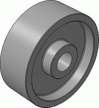
Rice. 3.54. gear blank
3. Select the entire part (the topmost element of the construction tree) and execute the Part Properties command from the context menu. Assign the parts to some other color more reminiscent of steel and set the optical properties to the following values:
· General color – 25 %;
Diffusion - 50%;
Specularity - 60%;
Shine - 40%;
Radiation - 85%.
4. Now let's start creating holes in the wheel disk and a keyway in the hub. Select a plane in the construction tree ZY and start the sketching process. In this sketch, place four holes with a diameter of 83.7 mm. The centers of the holes must lie on a circle with a diameter of 258 mm (see Fig. 2.143). The profile of the keyway cutout can simply be copied from the detail drawing of the gear and drawn a little (Fig. 3.55).

Rice. 3.55. Sketch for cutting holes in the discs and the keyway in the hub
Note
In this and subsequent sketch drawings, the Grayscale display mode is disabled in the model. This is done so that the drawings in the book better show the lines of the sketch image (the sketch is shown with thick lines, and everything else is a wireframe display of the model when viewed normal to the sketch plane).
5. Complete the sketch and execute the Cut extrusion command, setting the extrusion direction to Two Directions and the extrusion amount to Through All for both directions. Please note that the same removal of material could be performed using two cutting operations: first, holes for the thickness of the disk, and then a groove for the width of the hub. However, the solution given here is more rational, when the profiles of all the cuts are collected in one sketch, and the cutting is carried out through the entire model (in both directions from the sketch plane). The resulting model is shown in fig. 3.56.
Rice. 3.56. Wheel model without ring gear
Now let's move on to the most difficult thing - the creation of a gear rim of the wheel. The formation will take place as follows: first, we will make one cut between the teeth in the wheel blank, then we will build a constructive axis that coincides with the geometric axis of the wheel, and copy the resulting cut in a circle (the number of copies will be equal to the number of teeth). It sounds easy to say, but it's not easy to do.
How to form the actual cut between the teeth? If we were to create a spur wheel, it would be easy. It would be enough to sketch the profile of the cutout between the teeth of the wheel in the end plane of the wheel, and then cut it out by extrusion through the entire wheel. However, we have a helical gear with a tooth line angle of 15°. In this case, the notch will pass along a curvilinear trajectory enveloping the surface of the wheel crown, the projection of which on the normal plane will make the specified angle with the wheel axis.
There are many ways to create such a cutout. They significantly depend on the modeling software offered by one or another graphic editor. In KOMPAS-3D, the most convenient and acceptable in terms of resource consumption are two methods for constructing cutouts for a helical gear.
First option - loft cutting. At the same time, sketches-sections are built in the wheel model, the planes of which are removed from the side surface of the wheel by a value l= i· b/ (n c – 1), where i– serial number sketch, b- wheel width nс – number of sections or sketches. The first sketch lies on the end plane of the ring gear, the last sketch lies on the opposite end plane, the rest are uniform. =l/d to, d to - pitch diameter gear wheel (Fig. 3.57).
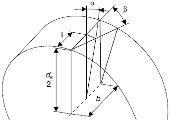
Rice. 3.57.l
This method is suitable for the software implementation of the ring gear, when it is possible to create a cycle in which one after another the offset planes will be built, and in them there are other flaws. Material that is cut between two adjacent sketches is still cut straight. From this conclusion - the more sketches, the more accurately the teeth in the wheel will turn out, but with too many teeth, their construction is significantly more difficult and the rebuilding of the ring gear slows down. Although, in principle, only 3-5 sketches are enough for not too wide wheels.
The second way is making a cut between the teeth by a kinematic operation. The essence of the method is that a segment of a spatial curve is constructed in the wheel model, imitating the line of inclination of the tooth. Along this curve, the profile is “stretched” further, since it is this method (as more accurate) that we will choose to form a cutout between the gear teeth.
Let's continue working on the model.
1. Select the end face (flat side face) of the wheel rim and build an auxiliary plane parallel to it at a distance of 2.5 mm (this is so that the sketch of the cutout in the wheel is placed in the same plane as in the gear, since the gear is 5 mm wider than the wheel). To perform this operation, use the Offset Plane tool of the Construction Geometry toolbar. Start the sketching process. In principle, the sketch can be placed anywhere along the pitch circle on the auxiliary plane. However, remember one of the recommendations for building three-dimensional models: it is desirable to create parts so that they can be placed as easily as possible in the assembly. Gear when assembling the gearbox, you will have to mate it with the gear, and since the engagement in the part under consideration is helical, it will not be so easy to do this (if the ring gear is cut carelessly). The solution suggests itself: it is necessary to create a cutout of the teeth on the wheel and gear so that immediately after insertion into the assembly they engage. This can be achieved by first cutting out exactly the pair of teeth in the wheel and gear that will be in engagement. For this reason, we created an offset plane rather than sketching directly on the side of the rim.
2. Draw auxiliary circles in the sketch, indicating the pitch diameter, as well as the line of protrusions and depressions of the teeth. Create a horizontal construction line through the center of the wheel (the sketch origin point). Using the Auxiliary Straight Line tool of the Geometry panel, lay down six auxiliary lines down from this horizontal straight line so that they all pass z to ( z tripling (it will be easier to form a gear). Do not forget that we are building the teeth in a simplified way!
3. Attaching to the grid of auxiliary lines, build the contour of the cutout profile between the teeth (Fig. 3.58). Create regular arcs instead of involutes (3-point Arc command). These arcs must necessarily pass through the engagement points located at the intersection of the auxiliary pitch circle, as well as the first and fifth auxiliary and legs of the cut teeth. Finish editing the sketch.
Rice. 3.58. Sketch of the cutout profile between the teeth
4. Now the most interesting thing is the formation of a spiral guide. Switch to the Spatial Curves toolbar. In the model window, select the reference plane (the plane containing the cutout sketch) and click the Cylindrical Spiral button on the 3D Curves toolbar. Using the controls on the Build tab of the properties panel, set up the parameters of the created helix as follows:
construction method - By the number of turns and pitch;
the number of turns - 0.04 (it is determined constructively during construction in such a way that the spiral turn is slightly larger than the width of the wheel);
pitch of turns - 4721.8 mm (as determined, described below);
· Construction direction – Reverse direction (reverse with respect to the normal to the base plane of the spiral);
winding direction - Right;
The initial angle of the helix is 182°. This is the angle that defines the beginning of the first turn on the reference plane of the helix. It is determined approximately during construction (it is necessary that the start of the coil falls inside the contour of the cutout sketch between the teeth - exact value doesn't matter);
The starting point of the spiral - coincides with the point of origin of the reference plane (that is, it lies on the wheel axis);
· the diameter of the spiral turns (set on the Diameter tab of the properties panel) – equal to the pitch diameter of the wheel (404 mm).
Click the Create object button to complete the spiral formation (Fig. 3.59). The resulting object only remotely resembles a spiral due to the large given pitch of the turns and their extremely small number. However, from a mathematical point of view, this is precisely a spiral. For us, the main thing is that this curve ideally describes the spatial position of the tooth inclination line in a helical gear.
Rice. 3.59. Building a spiral guide for cutting material between the teeth (model display method - No hidden lines)
Surely everything written above caused you more questions than it gave answers regarding how to form a guide for building oblique teeth. It is still not clear where the pitch of the turns came from, so huge and at the same time so accurate, where the spiral parameters indicate the angle of its rise (depending on the angle of inclination of the tooth line) and why it can be argued that this spiral is the line of inclination of the wheel teeth .
= h/ l, where h- Helix height l- the length of the turns. Accordingly, the length and height of the turns can be determined from the equations: h= t· n and l =d· n, where t- pitch of the helix n is the number of turns of the helix and dt/ (d). t= d
Now everything is ready for kinematic cutting.
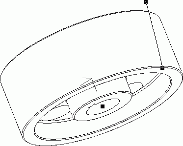
1. Click the Cut kinematically button on the Part Editing toolbar. Click the Section button on the Parameters tab of the property bar, then immediately select the cutout profile sketch between the teeth in the design tree. The sketch in the model window and in the construction tree should be highlighted in red, and its name should be displayed in the field to the right of the Section button (I have Sketch: 3). Next, click the Trajectory button and select the helix in the construction tree or directly on the model. A phantom of the cutting operation will be immediately formed on the model. Make sure that in the group of buttons Section movement the button Save angle of inclination is pressed. Confirm the operation by clicking the Create object button. We have received the first cutout in the ring gear of the wheel (Fig. 3.60).

Rice. 3.60. Cutting teeth in a wheel
2. Further refinement of the model does not cause any particular difficulties, because we only need to multiply the constructed cutout. Switch to the Construction Geometry panel and click the Conic Surface Axis button. Then click in the model on the inside surface of the shaft hole. If the Auto-create button is pressed on the special construction panel, you will immediately get the desired auxiliary axis. Otherwise, you will have to click the Create object button yourself.
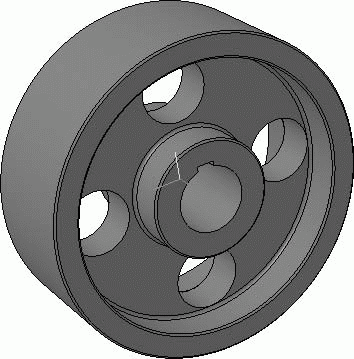
3. Return to the Edit Part panel, where click the Array by Concentric Grid button. In the part construction tree, select the kinematic cutting operation as an object for copying. After that, click the Array Axis button on the property bar, and in the construction tree, select the line corresponding to the created axis of the conical surface. A preliminary phantom of the array is drawn in the model window (by default, there are only four copies in it). In field N 2 on the properties panel, enter the number of copies in the annular direction, equal to the number of teeth of the wheel (71), and click the Create object button. A three-dimensional model of a helical gear is completed (Fig. 3.61)! For a better representation of the model, hide the helix, minor axis, and plane using the Hide command from the context menu of the construction tree.
Rice. 3.61. 3D model of a helical gear
You can familiarize yourself with this model by downloading it from the file Cogwheel.m3d, which is located in the Examples\Chapter 3\Spur Gear folder on the CD that accompanies the book.
If you have any difficulties at any stage of the build, do not despair. Any operation or sketch in the model can be viewed by running its editing. In addition, you can repeat the entire process of building a model step by step using the construction tree. There is always a horizontal bar or bar at the bottom of the tree. If you move the mouse pointer over it, it will take the form of a double-headed vertical arrow. By clicking on this plank, you can drag it up the tree with the mouse. In this case, all operations that fall below the bar will be canceled for the model, that is, excluded from the calculation. This function provides a very good opportunity for teaching modeling in KOMPAS-3D: you raise the bar to the very top of the tree, leaving only the base of the part included in the calculation, and then gradually lower it down, paying attention to those operations that caused you difficulties. In the course of lowering the bar, the model will be rebuilt, completely repeating all the stages of construction.
Note
As you remember, KOMPAS-3D V10 has a very convenient context menu command Pointer under the selected object, which allows you to move the bar directly under the selected element in the construction tree.
The construction tree also allows you to change the order of shaping operations. By clicking on a node denoting a particular 3D operation, you can move it to any place in the tree. By clicking the Rebuild button after that, you will change the structure of the model, taking into account the changes in the tree. However, editing a part using drag and drop operations is fraught with large quantity errors after rebuild. For example, you can drag a Fillet operation above a shaping operation that creates edges that are then used to fillet. And if an error occurs, then all settings for the Rounding operation will be lost. Even if after that you return the operation to its place, the error will not disappear, since all connections have been lost (faces and edges specified during rounding).
Create a detail drawing of a gear
At the beginning of this section, another practical example was mentioned regarding the preparation of drawings in the KOMPAS-Graph system. In order not to deviate from the logic of the presentation of the material, as this example, we will complete the design drawing of a gear part included in the newly designed gearbox. This example will be small compared to the previous one. Nevertheless, it contains important information on the formation of detailed drawings, which occupy a significant share among all design documentation accompanying the release of a complex product. I will not describe in detail the nuances of constructing geometry, since I believe that all of the above is enough to create images of any complexity. We will have to draw very little on the new drawing, since the main image of the wheel will be inserted from the gearbox assembly drawing.
Let's create a drawing of the wheel on a new document (if you wish, you can place this drawing in the same document with the image of the gearbox, adding to it new leaf). Create a new document and set its parameters as follows: format - A3, orientation - horizontal, leave the design style as default. Form in document the new kind with a scale of 1:2 and name it Cogwheel. Place the origin of the view in the middle of the sheet, a little closer to its left side. Now you can start building the drawing.
1. Open the document containing the gearbox assembly drawing. Click the Select layer by picking button on the Selection toolbar. By clicking on the wheel image, select the gear layer. Use the keyboard shortcut Ctrl+C to copy the selected drawing elements to the clipboard. Specify the intersection point of the wheel axes as the anchor point (point of origin of the top view coordinates).
2. Switch to the view window of the newly created document. Make sure the current view is Cogwheel. Press the keyboard shortcut Ctrl+V and paste the image of the wheel into the drawing, snapping it to the origin of the view. Select the pasted image, then using the Rotate command, position the wheel vertically by rotating it 90° around the origin.
3. Slightly to the right of the inserted image, construct the profile of the hole in the hub, assuming that the depth of the keyway with a hole diameter of 85 mm is 5.4 mm, and the width of the groove is 20 mm. Starting from the hole profile, edit the wheel section by drawing the keyway in the section (Fig. 2.132).
Rice. 2.132. Finalization of the gear drawing
4. Remove all construction geometry from the drawing. You won't have to edit the wheel image itself anymore.
Now you can proceed to the design of the detailed drawing. Let's start with sizing. As noted earlier, the detail drawing must contain all the dimensions of the product necessary and sufficient for its manufacture and processing.
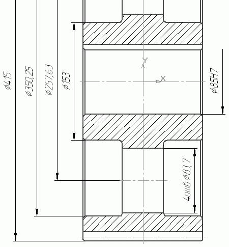
Using the Linear Dimension tool, sequentially set the dimensions of the following diameters (Fig. 2.133):
Wheel hubs;
The placement of holes in the disks and the diameter of one such hole;
Protrusions of the teeth of the wheel;
Holes in the hub (holes for the shaft) with an indication of the quality.
Rice. 2.133. Putting down the diametrical dimensions of the wheel
When forming a dimension inscription of these sizes, you should set the Auto checkbox in the dimension inscription settings window (this indicates the need to automatically determine the value of the face value), and also indicate the Zh icon in front of the face value. For the size of the hole in the disk, in the Text to field, enter the text 4 holes, indicating that there should be four holes of this diameter in the wheel. The pitch diameter in the drawing does not need to be indicated, since it will be given in the table of gear characteristics.
The task of constructing the size of the hole in the hub may not be quite simple (shown on the right in Fig. 2.133). This dimension cannot be snapped to two points because the top of the hole shows a sectional view of the keyway. In the drawings, such a diametrical dimension is indicated by being tied to only one extension line (this line indicates which hole this dimension refers to). To remove the top extension line, before the final fixation of the size on the property bar, go to the Parameters tab and release the Draw the second extension line button. Next, from the Arrow drop-down list (for the second extension line), select No Arrow. How to specify the quality was described above (of course, this quality must match the one indicated on the assembly drawing). Don't forget to check the Enable checkbox next to the field with the quality value so that it is displayed in the dimension text.
The next group of dimensions is also created using the Linear Dimension command, but these are no longer diametrical, but really linear dimensions. All the difference in their construction is only in the setting of the Symbol switcher in the Specify Dimensional Inscription window to the No position. These sizes include:
wheel width;
Distance from the side surface of the disk to the end of the rim (two dimensions are indicated on both sides);
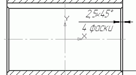
Designation of the chamfer parameters of the hole for the shaft and chamfers on the edges of the rim. Since in our wheel all these chamfers have the same parameters (2.5 45 °), the chamfer is indicated once, but the size indicates that there are four such chamfers on the wheel (Fig. 2.134).
Rice. 2.134. Chamfer size
To create such a dimension (see Fig. 2.134), after calling the dimension inscription settings window, do the following.
1. In the dimension inscription settings window, next to the Text after field, press the ґ45° button to add the corresponding sign after the nominal value.
2. Press the button >> in the lower right corner of the Dimension Inscription Setting window. After that, the dialog box will increase and in the upper right corner the Text field will appear under the dimension inscription, where you should enter the text 4 chamfers.
3. Press the OK button and fix the position of the dimension inscription.
On the wheel drawing, it is still necessary to put down the rounding radii at the transition points of the disk to the rim and hub. To do this, use the Radial Dimension command on the Dimensions panel. To form this dimension, simply specify the arc whose radius you want to put down. However, in our drawing, all these arcs have too small a radius, and the dimension arrow (respectively, the dimension inscription) does not fit in the gap between the rounding center and the reference point of the radial dimension. By default, the KOMPAS system places this dimension outside the arc of a circle, while drawing the arc with a thin line (Fig. 2.135, a). Agree, it doesn't look pretty. To adjust the position of the arrowhead and the dimension inscription during dimension entry (more precisely, after specifying the arc, but before the final dimension fixation), go to the Parameters tab on the property bar. From the Text Placement drop-down list, select Manual, and then click the Inside Arrows button. Now you can build a normal radial size even for the smallest arcs (Fig. 2.135, b).
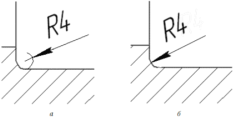
Rice. 2.135. Radial dimension for arcs of small radius: default setting suggested by the system ( a), and the view after settings ( b)
The next step in the design will be setting the roughness on the drawing (that is, the allowable values of microroughness of the surface of the product). The designation of roughness is entered on the drawing to indicate the requirements for the quality of processing of a particular surface of the manufactured product.
As well as positions in the drawing, all roughness symbols can be put down in one call of the Roughness command (it is also located on the Symbols toolbar). To form a roughness sign, do the following.
1. Select a sign type in the Type radio button group on the property bar.
2. If necessary, in a special window, enter the text that will be displayed on the roughness sign (Fig. 2.136). This window is called by clicking on the Text field of the properties panel. As a rule, in this window, the maximum allowable (after finishing) arithmetic mean deviation of the profile of protrusions and depressions of the product surface is entered. Ra.
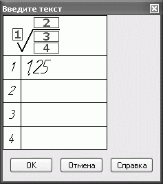
Rice. 2.136. The window for entering the inscriptions of the roughness sign
3. Having finished entering the text, specify the line on the drawing to which the image of the roughness sign will be attached, and then fix the sign itself at any point on this line.
Advice
You can enter a roughness value (R a , R z or R max) without opening the Enter Text window. To do this, right-click on the Text field of the properties panel and select the required value from the menu that appears. This is also convenient because the menu contains only normalized (admissible) roughness values.
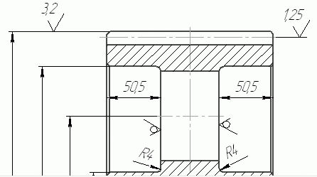
Using the Roughness command, construct the roughness signs as follows (Fig. 2.137):
One roughness sign each, indicating that the surface does not require additional processing (button No material layer removal
on the properties panel), on both sides of the disk;
Rice. 2.137. Roughness markings
Roughness sign Without specifying the type of processing (button
) with a roughness value of 1.25 µm (on a scale Ra) on the line of engagement;
Three signs of roughness, also without indicating the type of processing, but with a roughness of 3.2 microns on the end surfaces of the wheel, as well as on the surface of the tops of the teeth;
Another sign of roughness (1.25 microns) on the inner surface of the hole for the shaft in the wheel hub.
In detail drawings, there should almost always be a sign of unspecified roughness. It indicates the required roughness for product surfaces for which the roughness is not indicated on the drawing itself. The sign of unspecified roughness is placed in the upper right corner of the drawing.
To add this symbol to the drawing, execute the menu command Insert? Unspecified roughness? Input. In the appeared window Sign of unspecified roughness, you can set appearance sign: select its type, enter text (roughness value), and add a sign in brackets. When you have finished setting up the display of the sign of an unspecified roughness, execute the menu command Insert? Unspecified roughness? Accommodation. By default, the sign is placed in the upper right corner of the drawing sheet (Fig. 2.138), but if necessary, you can edit its placement by dragging it over the characteristic point.

Rice. 2.138. Sign of unspecified roughness
On the wheel drawing, it remains to put down the tolerances of the forms and relative position surfaces. Before this, it is necessary to select and designate the base on the drawing, since all deviations are affixed to a specific base.
As a base surface, we select the holes for the shaft in the wheel. Click the Datum button on the Symbols toolbar, click the line denoting the surface of the hole in the section, and then fix the position of the datum symbol. You do not need to enter the text, since the system will automatically set the letter designation of the base (in our case - A, since there are no other bases, cuts, cuts or leader lines in the drawing). Now you can put down shape and location tolerances.
As an example, consider setting the tolerance for radial runout of the surface of the teeth of a wheel.
1. Click the Shape Tolerance button on the Symbols toolbar. On the property bar, click the Create table in semi-automatic mode button
A window will open that allows you to create and fill in the tolerance table (Fig. 2.139).
Rice. 2.139. Dialog box Tolerance designation
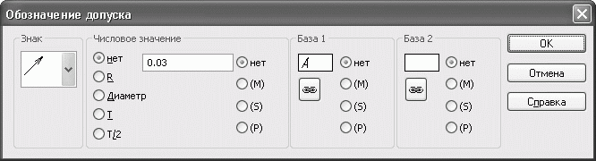
2. From the Sign drop-down list in the Tolerance Symbol window, select the icon that indicates the runout tolerance. In the area text box Numeric value enter the tolerance value, and in the Base 1 area, enter the designation of the base relative to which the tolerance is indicated. Using the button located under the text field with the base designation, you can call up a window with a list of all available bases in the document.
Advice
The tolerance value, which is specified in the table, must be consistent with the standards. Instead of entering it manually, you can call up a menu listing all standard values by double-clicking on the text field in the Numeric Value area.
3. Having generated the tolerance table, specify its reference point on the drawing. After that, you need to create an arrow pointing to the surface to which this tolerance applies. To do this, click on the branch button with an arrow
on the dedicated control panel. Create an arrow by anchoring its origin to one of the points on the table outline, and fixing the pointer on the surface for which the runout tolerance is set.
4. To fix the tolerance, click the Create object button.
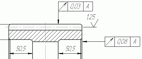
5. Similarly, perform the tolerance of the end runout of the wheel (the designation and base are the same, and the tolerance value is 0.08).
The created designations of runout tolerances of surfaces are shown in fig. 2.140.
Rice. 2.140. Form and surface tolerances
Perform another form tolerance, namely the parallelism tolerance of the side surfaces of the wheel. It does not require binding to the base, so its designation is not in the table. Parallelism is checked for two surfaces, so that the tolerance table is attached to one of them (Fig. 2.141). To specify the reference (base) surface after creating a branch with an arrow, click the Branch with triangle button
and build it the same way as the arrow.
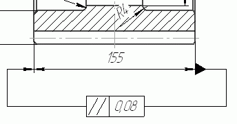
Rice. 2.141. Surface parallelism tolerance
Using the acquired skills, try to independently put down the dimensions, roughness, tolerances of shapes and placement of surfaces for the hole profile in the wheel (Fig. 2.142).
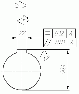
Rice. 2.142. Dimensions, roughness and tolerances of the hole profile in the wheel hub
On detail drawings gear wheels always post a wheel parameter table. Let's create it.
Click the Enter Table button on the Symbols toolbar. Specify the anchor point of the upper left corner of the table in the drawing (the table itself should be placed on the right side of the drawing, right under the unspecified roughness sign), set the number of columns to 3, and the number of rows to 9. After that, dragging the borders between the columns, adjust the width of the columns as follows so that the first one is the widest one, and the other two are smaller. Fill in the table with various calculated data (module, number of teeth, pitch diameter, etc.). You can see an example of this table in the file _GEAR.cdw (located in the Examples folderChapter 2 Cylindrical Reducer of the CD attached to the book), which contains the described detailed drawing. The set of these data may differ from that considered in the example. After the design table is completely filled in, select it and use the Shift tool of the Editing toolbar to edit its placement so that its right border coincides with the right border of the drawing sheet.
And the last thing left to add to this drawing is the technical requirements.
Execute the menu command Insert? Technical requirements? Input. A new text document window will open, where you can type the text of the technical requirements. For example:
1. Forming slopes 3°.
2. Rounding radii R2max.
3. Unspecified limit deviations of dimensions: shafts h14, holes H14, others IT14/2.
After typing the technical requirements, save them and close the KOMPAS-Graph text editor window. To edit the placement of specifications on a drawing, use the Insert? Technical requirements? Accommodation.
That's all. A training example of creating a detailed drawing (Fig. 2.143), and with it the entire section on practical drawing, finished.
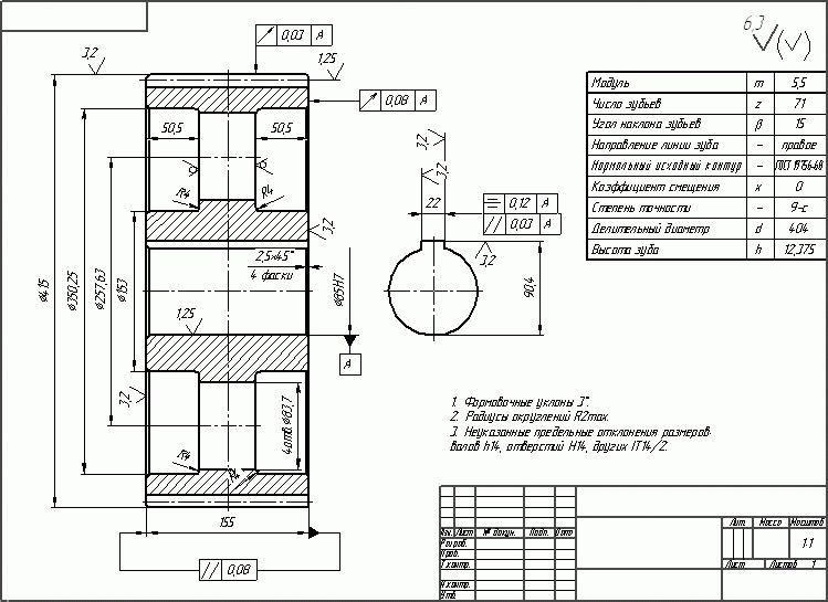
Rice. 2.143. Detail drawing of a gear wheel
From the book KOMPAS-3D V10 100% author Kidruk Maxim Ivanovich 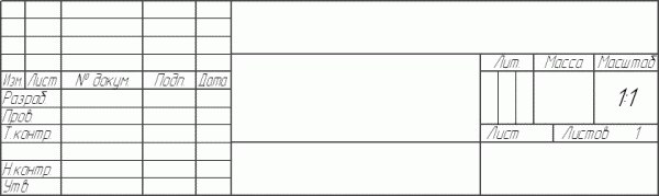
Making a drawing You most likely noticed that when creating a new drawing, an A4 sheet is placed on it. Surely you have a question about how you can change the format, orientation, or even the title block of the sheet. After all, how to assign a format for
From the book KOMPAS-3D V10 100% author Kidruk Maxim Ivanovich 
Creating an assembly drawing of a single-stage spur gearbox To begin with, a few words about what we will draw. A gearbox is a machine-building mechanism designed to coordinate the operating parameters of the electric motor and the working body of the machine
author Sokolova Tatyana Yurievna From the AutoCAD 2009 student book. Tutorial author Sokolova Tatyana Yurievna From the AutoCAD 2010 book author Orlov Andrey Alexandrovich 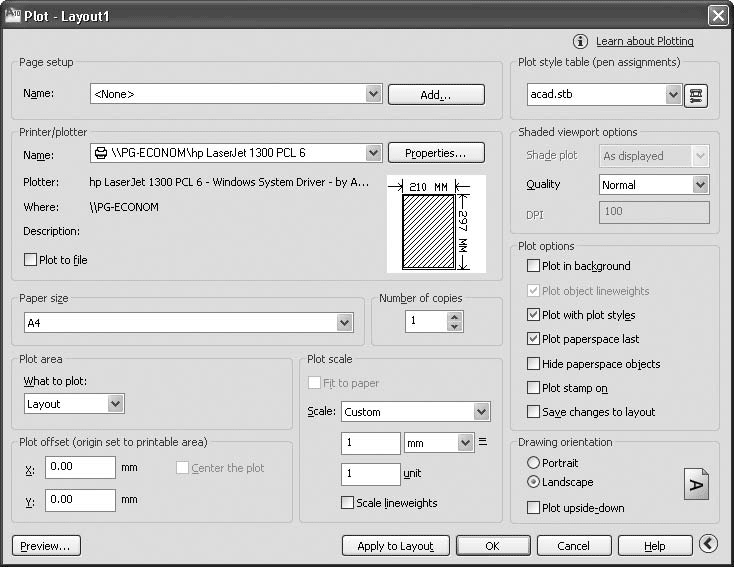
Printing a Drawing Before you start printing, you need to make sure that the printer or plotter is turned on and connected to the computer. Also check that paper is loaded in it. Printing is performed from the Plot (Print) dialog box (Fig. 8.29), which is launched when
author Sokolova Tatyana YurievnaDrawing Walk The 3DWALK command interactively changes the view of a 3D drawing, making it appear as if the viewer is walking around the model. The command is called from the drop-down menu View ? Walk and Fly? Walk or by clicking the Walk icon in the Walk and Fly or 3D Navigation floating toolbar.
From the book AutoCAD 2008 for the student: a popular tutorial author Sokolova Tatyana YurievnaDrawing Flying The 3DFLY command interactively changes the view of a 3D drawing so that the viewer appears to be flying through the model. The command is called from the drop-down menu View ? Walk and Fly? Fly or by clicking the Fly icon on the Walk and Fly or 3D Navigation floating toolbar. Fly
author Sokolova Tatyana Yurievna From AutoCAD 2009 Book Tutorial author Sokolova Tatyana YurievnaDrawing Flying The 3DFLY command interactively changes the view of a 3D drawing so that the viewer appears to be flying through the model. The command is called from the drop-down menu View ? Walk and Fly? Fly or by clicking the Fly icon on the Walk and Fly or 3D Navigation floating toolbar. Fly
From the ArchiCAD book. Started! author Orlov Andrey AlexandrovichChapter 8 Design drawing Development of the project is completed by the release of project documentation, which is based on drawings drawn up in accordance with accepted standards. Making a drawing is a complex and responsible work, on the implementation of which the
From the AutoCAD 2009 book author Orlov Andrey Alexandrovich 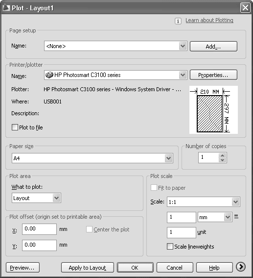
Printing a Drawing Before you start printing, you need to make sure that the printer or plotter is turned on and connected to the computer. Also make sure that paper is loaded in it. Printing is performed from the Plot (Print) dialog box (Fig. 8.33), which is launched
author Sokolova Tatyana YurievnaDrawing Walk The 3DWALK command interactively changes the view of a 3D drawing, making it appear as if the viewer is walking around the model. The command is called from the drop-down menu View ? Walk and Fly? Walk or by clicking the Walk icon on the floating Walk and Fly or 3D Navigation toolbar.
From the AutoCAD 2009 book. Let's get started! author Sokolova Tatyana YurievnaDrawing Flying The 3DFLY command interactively changes the view of a 3D drawing so that the viewer appears to be flying through the model. Is the command invoked from the View drop-down menu? Walk and Fly? Fly or by clicking on the Fly icon on the floating Walk and
From the book ArchiCAD 11 author Dneprov Alexander GChapter 10 Designing a drawing Dimensioning Callout labels Setting units of measurement A virtual building allows you to create a complete impression of the projected object, but you can build this object only if you have a set of design documentation, a basis
From the book KOMPAS-3D for students and schoolchildren. Drawing, computer science, geometry author Bolshakov Vladimir5.3.2. Creating an associative drawing of a support Creating a drawing Execute the command File | Create | Drawing.Creating Standard Views1. Execute the command Insert | View from model | Standard.2. Open the document Support.3. On the Options tab of the Property bar, in the Orientation field
From the book Magazine `Computerra` No. 754 author Computerra magazineTopic: Building a Gear in KOMPAS Shaft2D
Purpose: Familiarization with the program of the design system KOMPAS-
Shaft2D and the design of the gear wheel of the transmission mechanism of the machine.
Plan: 1. Gear wheel, main elements
2. Questions and task
1. Gear, main elements
Gear
- This is a mechanism that transmits rotational motion from one shaft to another using gears or wheels and racks. Gears are used as independent units(reducers) or are included in other machines as integral assembly units.
For transmission rotary motion shafts whose axes are parallel, apply cylindrical gears; when crossing the axes at a certain angle - bevel gears. Very often used worm gears providing great gear ratio and significant torque. To convert rotational motion into translational and vice versa, rack and pinion gears are used,
consisting of a cylindrical wheel and a rail.
The main elements of a gear wheel are teeth - protrusions on the wheel rim that transmit motion by engaging with the same protrusions of another wheel or rack.
A spur gear is a cylinder on the surface of which teeth are cut. According to the location of the teeth on the surface of the rim, gears are divided into: spur, helical,
chevron and crooked.
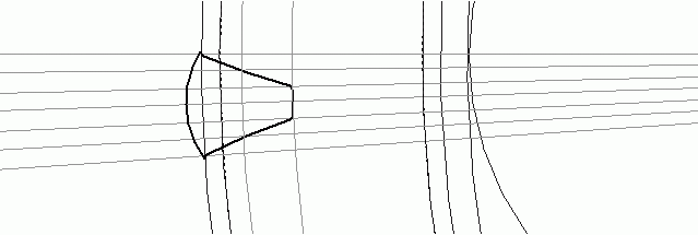
Picture 1 - The main elements of the gear
The design of gears can be different, but they all have the same type of elements common to all types of wheels, which, according to GOST
16530-83 were assigned the names indicated in (Fig. 1).
Imaginary cylinders in gears are called initial circles, and their projections onto the plane are called initial circles.
The initial circle divides each tooth into two parts - the head (upper part) and the stem (lower part). If only one gear is considered, then this circle is called a pitch circle. Circle,
limiting the projection of the heads of the teeth, is called the circumference of the protrusions; the circle limiting the projections of the depressions - the circumference of the depressions.
Working drawings of cylindrical gears are performed in accordance with GOST 2.403 - 75. On the working drawings of gears, the following should be indicated: the diameter of the circumference of the protrusions, the width of the gear rim:
dimensions of chamfers or radii of curvature on the end edges of the cylinder
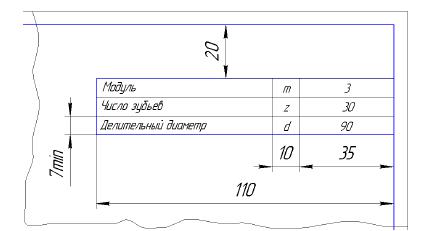
protrusions and other dimensions necessary for the implementation of the wheel. In the upper right part of the drawing, a table of parameters for the gear rim of the wheel is placed. The dimensions of the table and its location are shown in Fig.2. In the first part of the table, the basic data for the manufacture of the ring gear are placed, in the second - for control, in the third - for reference. On the training drawings an abbreviated table is placed indicating the module m, the number of teeth Z and
pitch circle diameter Dd.
Figure 2 - Table field
To the beginning of the lecture
2. Creating a drawing of a gear wheel part in Compass
1 Create a Drawing document, set the A3 format, the orientation is horizontal.
2 Call the Shafts and Mechanical Transmissions 2d library by clicking on the Library Manager button on the standard toolbar. Select the Calculation and construction tab. Double click on the required library.
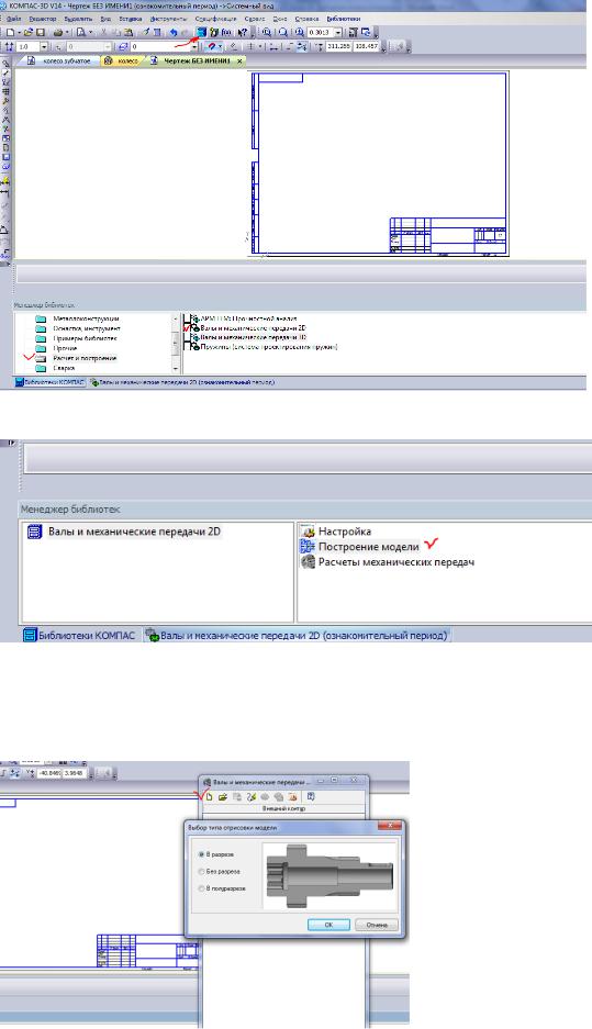
3 Double-click the Build Model command.
To the beginning of the lecture
4. In the window, click Create a new model, we will build in a section.
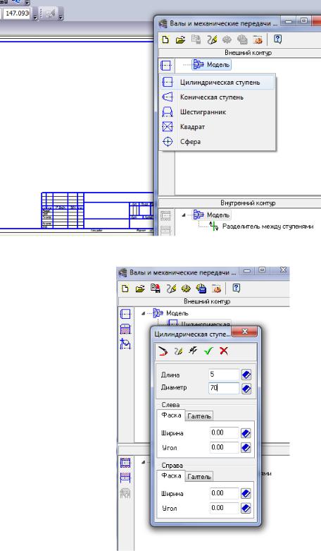
5 We fix the first point of the image and proceed to the construction of a drawing of a gear.
5.1 First, let's build the protruding part of the hub. In the outer contour, select the Cylindrical step.
We set its dimensions: diameter 70 mm, length - 5 mm.
Click the OK button (green arrow).
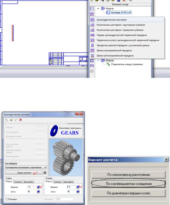
5.2 We will draw a spur gear, then in the Elements of mechanical transmission tab, select the Cylindrical gear.
5.2 Set the chamfers on the right and left by 1.6 mm and start the calculation by the offset coefficients, because in our case, we do not specify a specific gear train.
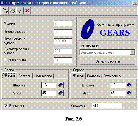
The External Gear Geometry Calculation dialog box opens, prompting you to enter the appropriate data for the wheel and pinion.
5.3 In the Page 1 tab, enter the values of the transmission parameters, the number of teeth, the module, the width of the ring gear. The rest of the fields can be left unchanged. Let's go to the second page.
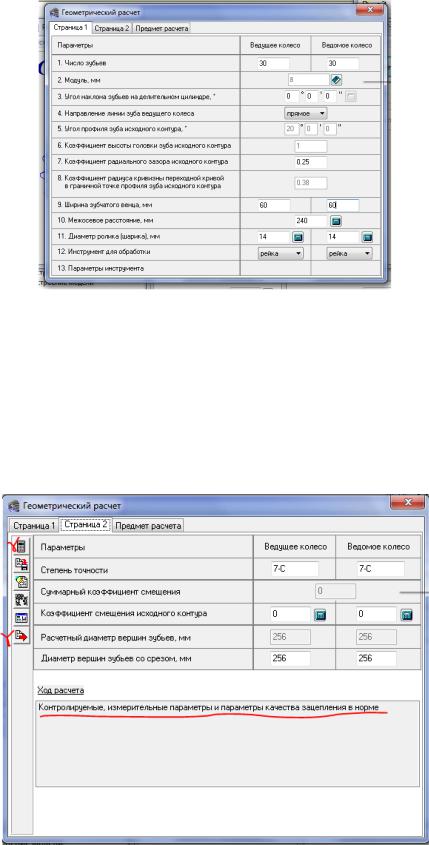
To the beginning of the lecture
To the beginning of the lecture
5.9 We return to the outer contour and create annular grooves and holes (additional constructions).
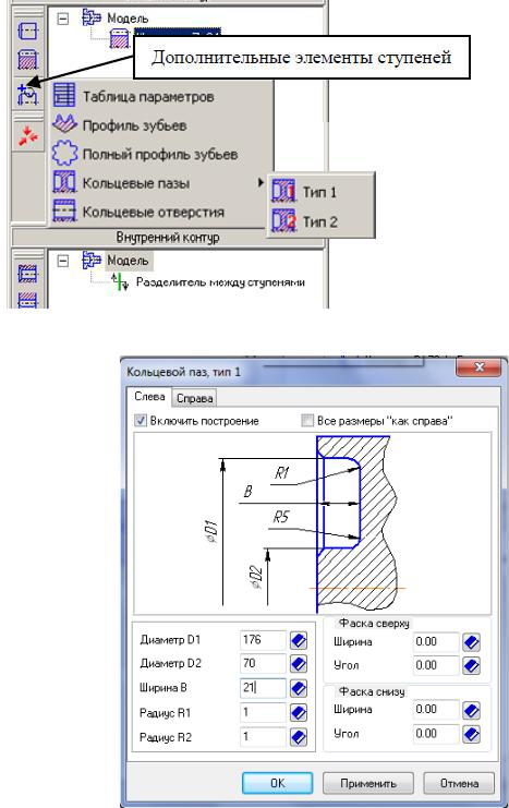
Fill in the fields on the tab on the left: diameter, width, radius.
Open the second tab on the Right and enter the same values in the corresponding fields. Click OK.
In the Annular Holes dialog box, fill in the radius of the center of the holes, the radius of the hole, the number of holes.