GOST 2185-66 establishes center distances a W, nominal gear ratios and gear width coefficients ψ ba and gives recommended combinations of center distances and general nominal gear ratios for gears cylindrical gears, which are used in two- and three-stage pump gearboxes for general purposes, which makes it possible for serial production of gearboxes.
Center distances
The center distances of the gearboxes a w are given in table. 49. The value of the interaxial distance is determined by calculating the fatigue contact strength of the tooth surfaces or is chosen structurally depending on the overall dimensions of the driven machine. In table 50 and 51 show the standard-recommended center distances for two- and three-stage gearboxes and their distribution among individual stages.
Table 49
Center distances of gearboxes, mm
Note. The preferred row is first.
Table 50
Center distances of two-stage three-axle gearboxes, mm

Table 51
Center distances of three-stage gearboxes, mm
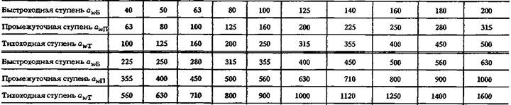
Table 52
Notes
2. For gearboxes that must be kinematically coordinated with each other, it is allowed to select gear ratios from the R40 series (GOST 8032-84).
3. Actual values gear ratios u f should not differ from the nominal values by more than 2.5% at u ≤ 4.5 and by 4% at u > 4.5.
Table 53
General gear ratios and total. two-stage gearboxes
Notes:
2. The actual values of gear ratios u f should not differ from the nominal values by more than 4%.
Table 54
General gear ratios and total. three-stage gearboxes
Notes:
1. For all gearboxes, the first row should be preferred to the second.
2. The actual values of gear ratios and f should not differ from the nominal values by more than 4%.
Gear ratios
Nominal gear ratios must correspond to those indicated in the table. 52.
The distribution of the total gear ratio between individual gear stages in two- and three-stage gearboxes (Tables 55 and 56) is carried out subject to the same use of the contact strength of the teeth with the same hardness of their surfaces, the same coefficients of the width of the teeth of the wheels of all stages and the distribution of center distances between the individual stages, as given in table. 50 and 5). In two-stage gearboxes with coaxial shafts in one horizontal plane For a given distribution of gear ratios between stages, with identical center distances, to fulfill the condition of equal strength, it is necessary to use gears with different width ratios.
Table 55
Distribution of total gear ratios in two-stage three-axle gearboxes across individual gear stages

Table 56
Distribution of total gear ratios in three-stage gearboxes across individual gear stages

Table 57
Distribution of total gear ratios in two-stage biaxial (coaxial) gearboxes with horizontal shafts in the same plane along individual gear stages

If the first stage has a width coefficient ψ bа = 0.4, then the second stage must have a coefficient ψ bа of at least 0.6 with the same materials of gears and wheels and the hardness of the tooth surfaces.
The gear ratios of the individual stages of these gearboxes (Table 53) are set under the condition of close contact strength and equal immersion in the oil bath of the gears of the high-speed and low-speed stages during dipping lubrication.
Gear width
The width of the gears b depends on the width coefficient ψ bа: b = ψ bа а w. The values of the gear width coefficient ψ bа (GOST 2185-66) are given in table. 58.
Gear width values are rounded to the nearest number from the R20 series according to GOST 8032-84. Exit groove width cutting tool in chevron gears is included in the width b. For different widths of mating gears, the value of the coefficient ψ bа is taken gear wheel with a smaller width.
When choosing the width coefficient ψ bа, it is necessary to take into account the material of the gears and the type of heat treatment, manufacturing accuracy, peripheral speed, modulus and axial pitch, the nature of the load, gearbox design and a number of other factors. It is recommended to choose narrow wheels, since in this case higher manufacturing accuracy is obtained and the uneven distribution of load across the width caused by deformation of the shafts and inaccuracies in the manufacture and installation of the gearbox is significantly reduced. For the same reason, the ratio of gear width to diameter is not recommended. pitch circle take more than 2.5.
If the hardness of the tooth surfaces is HB ≤ 350, it is recommended to set the hardness of the gear teeth to be 30...50 units greater than the hardness of the wheel teeth. In cases where the hardness of the gear teeth is significantly greater than the hardness of the wheel teeth, the width of the gear should be 5... 10 mm larger than the width of the wheel. Otherwise, with the relative displacement of the gear and wheel during operation, an undesirable ledge is formed on the teeth of the wheel.
If the hardness of the tooth surfaces of both wheels is HB ≥ 350, the width of the wheels can be assumed to be the same. For wheels with cemented, surface-hardened teeth, the width coefficient ψ bа is recommended to be no more than 0.4...0.5. As the length of the teeth increases, the errors arising during processing increase, which leads to greater difficulties in obtaining the required contact patch.
During surface hardening, warping of the teeth occurs; Moreover, with increasing wheel width, errors in the direction of the teeth increase. When using wide wheels, it is better to switch to chevron gearing, since the length of the tooth of one helix is about half the total width of the gear and errors in the direction of the teeth are significantly reduced.
In spur and helical gears, the width coefficient ψ bа should be no more than 0.4...0.6. For large values of the coefficient ψ bа it is necessary to use chevron gearing.
High-speed gears are manufactured with chevron gearing with a width coefficient ψ bа = 0.4... 1.0. With a cantilever arrangement of gears and wheels, it is recommended to select a width coefficient ψ bа not exceeding 0.4. With a further increase in the width of the wheel (if it is cantilevered), the load concentration along the length of the teeth increases greatly and the effect of using the wheel material decreases sharply.
Table 58
Gear width ratio
Modules
The module values for spur gears of gearboxes (GOST 9563-60) are given in table. 59. The magnitude of the module is determined based on the bending strength of the teeth. If possible, choose the smallest modulus values, since gears with small moduli are cut on gear cutting machines with greater accuracy and better surface finish, have lower mass and lower friction losses in meshing. With surface hardening, the shape of their teeth is less distorted and good and faster gearing is obtained.
If the gear wheel must operate at extreme contact stresses, then the value of the modulus obtained when calculating bending is recommended to be increased by 10...15%, since chipping of the tooth surfaces weakens them cross section and tooth fracture may occur.
Table 59
Module values t, mm
Note. When assigning module values, the first row is preferable.
Tooth line angles
The angles of inclination of the teeth in helical gears should be 8...10 0. In helical gears with a tooth angle of more than 10°, it is necessary to install either angular contact bearings with an increased contact angle, or in a support with a radial bearing, an additional thrust bearing must be installed, which increases the cost of the design and requires more reliable and complex end mounting of the bearings on the shafts and in the housings .
Reducing the angle of the teeth, especially in narrow wheels with a width coefficient ψ bа 0.2...0D, is undesirable, since the axial pitch may be greater than the width of the wheel. As a result, the axial overlap coefficient will be less than unity and the transmission will operate less smoothly, with greater dynamic loads, which leads to rapid wear and the appearance of defects on the surfaces of the teeth.
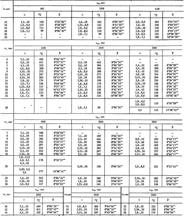
For the interaxal distances established by GOST in the table. Figure 60 shows the total number of teeth z ∑ and the angles of inclination of the teeth β on the index cylinder at certain intervals of gear ratios and modules in the normal section. These values are recommended for a width coefficient ψ ba ≥ 0.4 for uncorrected and corrected gearing with a shift coefficient x 1 = -x 2, respectively, for the gear and wheel, but can also be used for ψ ba< 0,4, но с проверкой, указанной в примечании к табл. 60.
The selection of the numbers of gear and wheel teeth depending on the accepted total number of teeth z ∑ and the gear ratio can be performed according to table. 62.
Table 60
Parameters of gears with helical wheels for ψ b a ≥ 0.4 (gearing uncorrected or corrected with shift coefficient x 1 = - x 2)

For chevron wheels the angle of inclination of the teeth β is equal to 25...35 0. The recommended parameters of gears with chevron wheels with uncorrected or corrected gearing with a shift coefficient x 1 = - 2, respectively, for the gear and wheel with a width coefficient ψ bа > 0.125 are given in Table. 61, where for standard center distances the total number of teeth z ∑ of the mating gear z 1 and wheel z 2 and the angles of inclination of the teeth β are given according to the accepted engagement modulus t in the range of gear ratios. The selection of the number of gear teeth z 1 and the number of wheel teeth z 2 depending on the accepted total number of teeth z ∑ and the gear ratio and gear is performed according to table. 62, where the numerator is the number of teeth of the wheel z 2, and the denominator is the total number of teeth z z of the mating gear and wheel. For each gear ratio value and the top line shows the smallest values z 2 /z ∑ , and the bottom line shows the largest values corresponding acceptable values the gear ratio in question. In the range of the smallest and highest values number of teeth z 2 /z ∑ can be any integer from the specified interval.
Continuation of the table. 60

Continuation of the table. 60

Note. Individual combinations of values α W , Z ∑ , m ; β can also be used for ψ ba< 0,4, но с проверкой соблюдения условия
or
Table 61
Parameters of gears with chevron wheels at ψ ba ≥ 0.125 (uncorrected or corrected gearing with a shift coefficient x 1 = -x 2)

Continuation of the table. 61

Continuation of the table. 61

It is necessary to pay attention to the fact that when selecting the number of teeth of a gear or wheel within 100 teeth, almost all gear cutting machines can cut wheels with any number of teeth. If the number of gear or wheel teeth exceeds 100, it is necessary to check the possibility of cutting them on gear cutting machines. For example, with z 1 = 50 and u = 2.5 according to table. 62 it is possible to use all values of the total numbers of teeth from 172 to 178 inclusive, which correspond to the values of the numbers of teeth of wheels z 2 from 122 to 128 inclusive. The number of wheel teeth z 2 = 127, as the original number, either do not use it or check the possibility of cutting according to the passport of the gear cutting machine.
The use of tooth numbers less than 17 is permissible after checking for the absence of undercutting of the teeth. Permissible deviations of gear ratios in table. 62 are within the limits as indicated in Note 3 to Table. 52.
When designing a gear, the material from which it will be made, the required diameter and the method of obtaining the workpiece are taken into account.
Steel gears
Gear wheels with a diameter of up to 150 mm in single and small-scale production are usually made from round steel; in medium-, large-scale and mass production, it is preferable to use forged or stamped blanks that have higher mechanical characteristics.
Gears are made integral with the shaft (shaft-gear) (Fig. 1, a, b) or made removable if the distance χ from tooth socket to keyway(Fig. 2) more than 2.5 m n for spur gears and 1.8 m e for conical ones. In the case of a one-piece design, the rigidity of the shaft increases and decreases total cost shaft and gears. The split design allows the gear and shaft to be made from different materials, and if one part breaks, leave the second without replacement. In Fig. 1, a shows the design of the gear shaft when the diameter of the tooth cavities d f1 exceeds shaft diameter d b.p.(diameter of the bearing flange), which ensures free exit of the tool when cutting teeth. At d f1< d б.п. (Fig. 1, b) cutter exit l out determined by drawing along its outer diameter D f, which is taken according to the table. 1 depending on m n and degree of transmission accuracy.
Spur gears with a diameter of up to 400... 500 mm (in in some cases up to 600 mm) can be forged, stamped, cast or welded.
Structural elements of gear wheels are shown in Fig. 3.
Typical designs of gear wheels and the basic relationships of their elements are shown in Fig. 4-8. Forged blanks for gear wheels are used with an outer diameter of the wheel of 4, d f< 200 мм or with narrow wheels (ψ ba< 0,2) diameter d a up to 400 mm. The stamping operation is highly productive and brings the shape of the workpiece as close as possible to the shape of the finished wheel. To facilitate filling with metal and releasing from the workpiece, the stamp, and therefore the workpiece, must have radii of curvature r ≥ 5 mm and stamping slopes γ ≥ 5° (Fig. 4). The inner surface of the rim, the outer surface of the hub and the disk surface of stamped wheels are usually not treated. The design of the cast wheel is shown in Fig. 5.
Rice. 1. Design of the shaft - gear Rice. 2. Gear element with key connection
 Rice. 3. Structural elements of wheels:
 a - cylindrical; b - conical; c - worm
 Rice. 4. Spur gears with d a ≤ 500mm:
a - stamped; b- forged; d st = 1.6d in; l st ≥ b subject to conditions
l st = (0.8...1.5)d in; δ o = 2.5m n +2, but not less than 8...10 mm; n=0.5mn for the rim, n for hub depending on diameter d in; D hole = 0.5(D o +d st); d hole = 15...25 mm; c = (0.2...0.3)b for stamped and c = (0.2...0.3)b for forged wheels
 Rice. 5. Cast spur gear with d a = 400...1000 mm:
b ≤ 200 mm d st = 1.6d in- for steel casting; d st = 1.8d in for iron casting; l st ≥ b
Rice. 5. Cast spur gear with d a = 400...1000 mm:
b ≤ 200 mm d st = 1.6d in- for steel casting; d st = 1.8d in for iron casting; l st ≥ bsubject to conditions l st = (0.8...1.5)d in; δ o = 2.5m n + 2 ≥ 8 mm;
n=0.5mn for rim n for the hub; c = H/5, but not less than 10 mm;
S = H/5, but not less than 10 mm; e = 0.8δ o; H= 0.8d in; H1 = 0.8H; R - inscribed arc of a circle
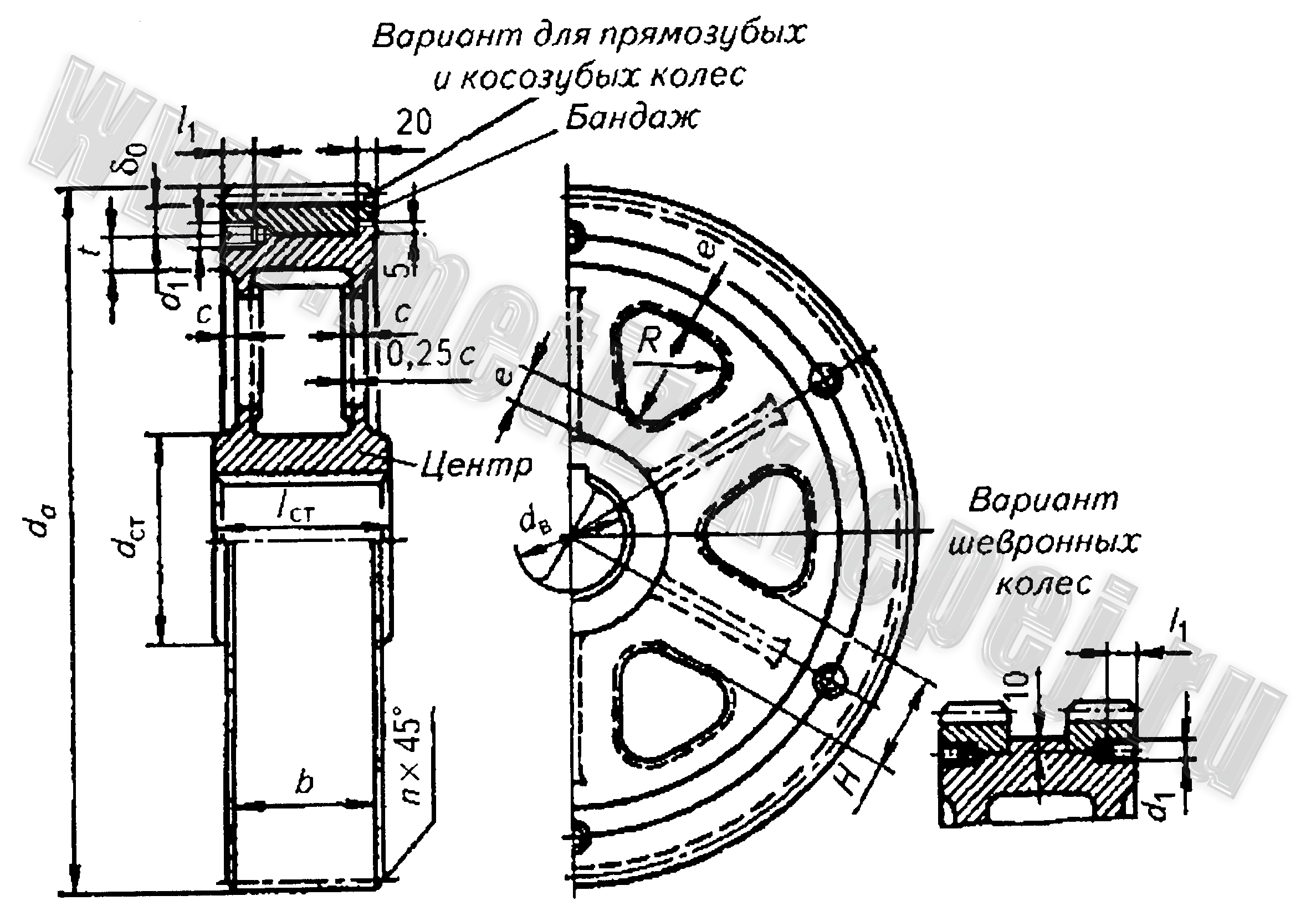 Rice. 6. Banded gear with d in over 600 mm: d st = 1.6d in- for steel casting; d st = 1.8d in- for cast iron; l st ≥ b
subject to conditions l st = (0.8...1.5)d in; c = 0.15b; δo = 4mn, but not less than 15 mm; t = δo; e = 0.8δ o; d 1 = (0.05...0.1)d in; l 1 = 3d 1;b ≥ 300 mm
 Rice. 7. Welded gear:
 l st = (0.8...1.5)d in ≥ b; d st = 1.6d in; δo = 2.5mn, but not less than 8 mm; s = 0.8c ; D hole = 0.5 (D o + d st); d hole = 15...20 mm. Seam legs: K a = 0.5d in; Kb = 0.1d in but not less than 4 mm. The ribs are welded with a seam K b
 Rice. 8. Chevron gear with a groove in the middle:
 l st = b + a; c = (0.3...0.35)(b + a); δ o = 4m n + 2; h = 2.5mn; a- depending on the module. For other dimensions, see fig. 4, 5
Hub sizes are selected according to the recommendations given below the figures. Hub length l st if possible, taken equal to the width of the wheel crown b, which ensures the smallest gearbox width. The ratio of the hub length to the shaft diameter must be at least 0.5. When the ratio is less than 0.8, a shoulder is provided on the shaft, eliminating the end runout of the wheel, against which the end of the wheel hub will be pressed. If according to the calculation conditions (see calculation of keyed and splined connections) l st > b, then it is advisable to move the hub along the axis of the wheel until one of its ends coincides with the end of the crown (see Fig. 3, a), which makes it possible to cut teeth on two wheels at once. Less often (for single-stage gearboxes) wheels are made with a hub protruding in both directions relative to the crown (Fig. 3, c), and teeth can be cut on only one wheel. With the same hub length and crown width, you can cut teeth on several wheels at the same time.
In order to save material, with large wheel diameters, spokes are used instead of a solid disk to connect the hub to the wheel crown. Large diameter gears (with outer diameter d a ≥ 600 mm) are sometimes made with bands (Fig. 6): the crown is forged steel (bandage), and the wheel center is made of steel or cast iron. The crown mates with the wheel center with a guaranteed interference fit. For greater reliability, screws are placed in the plane of connection between the crown and the center; connections are checked for crushing according to the material of the wheel center: with a steel wheel center [σ] cm ≥ 0.3σ t, with cast iron [σ] cm ≥ 0.4σ h.i., Where σ t- yield strength; σ v.i- the bending strength of cast iron.
When individually manufactured, wheels are sometimes welded (Fig. 7). With diameter d a ≥ 1500 mm For ease of assembly, the gears are made detachable - from two halves.
The ends of the teeth and rim are chamfered n=0.5mn, the size of which is rounded to a standard value of 1; 1.2; 1.6; 2; 2.5; 3; 4; 5.
Sharp edges at the ends of the hub are blunted with chamfers n x 45, the size of which is taken depending on the shaft diameter d:
Chevron gears (Fig. 8) are different from others cylindrical wheels greater width. Most often, chevron wheels are made with a groove in the middle, designed for the exit of a hob cutter that cuts the teeth. With known cutter dimensions, the groove width a determined by drawing. Approximately size a can be determined depending on the module m:
| m, mm a, mm | 1,5 27 | 2 32 | 2,5 37 | 3 42 | 3,5 47 | 4 53 | 5 60 | 6 67 | 7 75 | 8 85 | 10 100 |
Rest structural elements chevron wheels are taken according to the ratios indicated under Fig. 8.
Bevel gears are made from forged, stamped, cast or round rolled products (Fig. 9-11).
Bevel wheels with outer diameter of tooth tips d ae< 120 мм designed as shown in Fig. 9. In the case when the pitch cone angle σ < 30 ° , the wheel is made according to Fig. 9, a, at σ < 45 ° - according to fig. 9, b. If 30° ≤ σ ≤ 45°, both forms can be used. Stamped wheels (Fig. 10, a) are used in mass production. With the outer diameter of the vertices d ae ≥ 300 mm Cast conical wheels with stiffening ribs are also used.
The hub in bevel gears must be positioned so that there is clearance when the wheel is secured to the mandrel for cutting teeth. a> 0.5 m te for free exit of the tool, where i.e. external circumferential module (Fig. 11).
 Rice. 9. Bevel gears at d ae< 120 мм
:
Rice. 9. Bevel gears at d ae< 120 мм
:a- at δ < 30° ; b- at 5 >45°; hub diameter d st = 1.6d in; l st = (0.9...1.2)d in;
δ o = 2.5m n + 2, but not less than 10 mm; n=0.5mn
 Rice. 10. Bevel gears at d ae up to 500 mm: a - stamped; b - forged d st = 1.6d in; l st = (0.9...1.2) d c., but not less than 10 mm; c = (0.1...0.17)R e; n=0.5mn; dimensions D hole And d hole determine constructively
 Rice. 11. Fastening the bevel wheel when cutting teeth
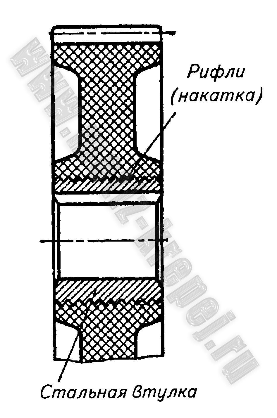 Rice. 12. Gear made of plastic with a steel bushing (hub) installed when molding the wheels
 Rice. 13.13. Gear wheel (gear) made of plastic with steel hub assembly
In the disks of cylindrical and bevel gears, holes with a diameter of d hole, used for fastening during processing on machines and during transportation. With large hole sizes, they serve to reduce the weight of the wheels, and in cast wheels also to allow the release of casting gases during casting.
Non-metallic gears.
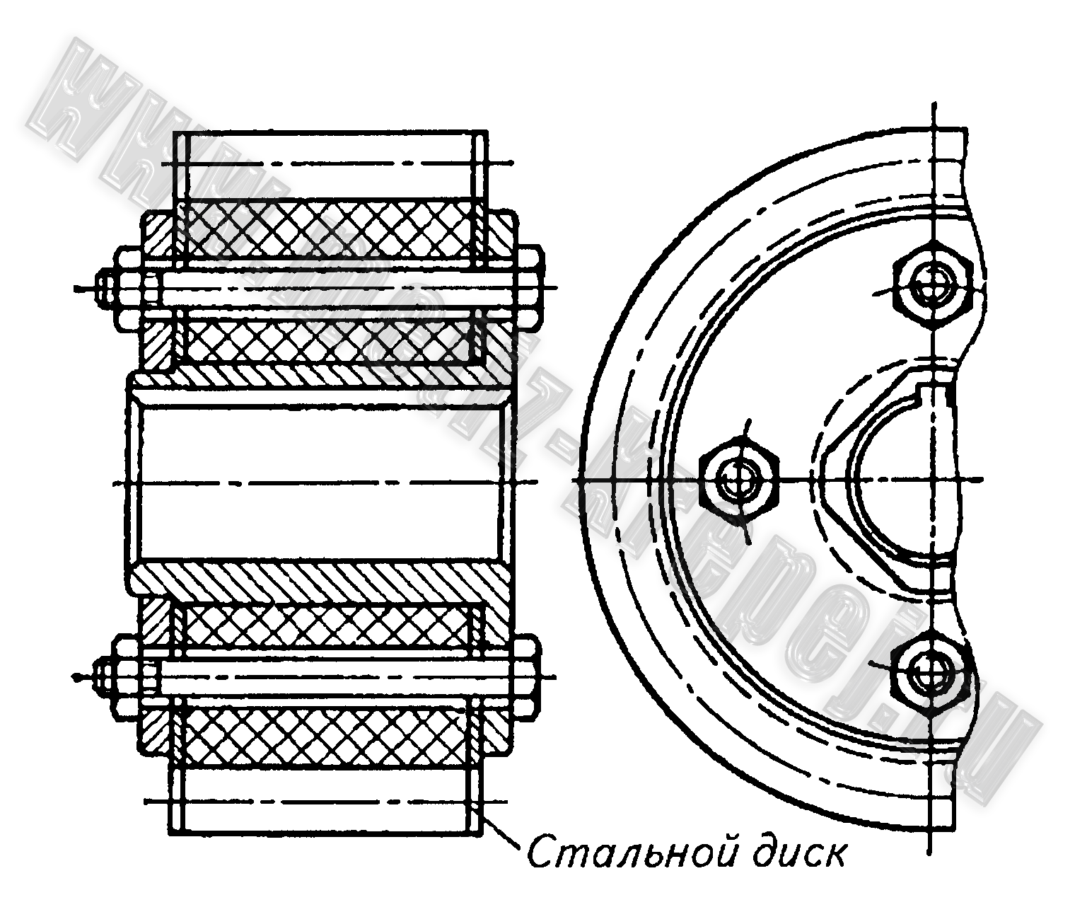
Non-metallic gears. Gears made of plastics (textolite, wood-plastics, polyamides, etc.) operate more silently than metal ones, which is of particular importance at high speeds. To reduce the coefficient of friction between the teeth, one gear is made of plastic, and the second is made of metal. Plastics have relatively low resistance to shearing and crushing, so in most cases a steel hub bushing, firmly connected to the wheel body, is used to transmit torque. In small wheels, the hub is installed during molding. For better grip, the outer surface of the hub is made grooved (knurled) (Fig. 12). To prevent chipping and chipping of individual layers of plastic, the edges of the teeth are protected with steel disks (Fig. 13). It is recommended to take the thickness of the disk equal to half the module, but not more than 8 mm and not less than 2 mm. Disc material - steel St.2, St.Z.
Gears large sizes usually made prefabricated from separate sections.
The width of a plastic gear is taken equal to the width of the metal wheel meshing with it or slightly less in order to avoid local wear and wear of teeth
| No. | Parameter name and dimension | Designation | Meaning | Determination method |
| 1. | Number of wheel teeth | z | count | |
| 2. | Module, mm | m | formula (3.1) | |
| 3. | Offset factor | X | formula (3.2) | |
| 4. | Equalization coefficient | D at | formula (3.3) | |
| 5. | Diameter of vertices, mm | d a | formula (3.4) | |
| 6. | Diameter of depressions, mm | d f | formula (3.5) | |
| 7. | Pitch diameter, mm | d | ||
| 8. | Main diameter, mm | d in | ||
| 9. | Tooth height, mm | h | formula (3.6) | |
| 10. | Pitch thickness, mm | S | ||
| 11. | Constant chord, mm | |||
| 12. | Height to constant chord, mm |
The report provides diagrams and measurement results, calculation formulas and calculation results. A conclusion is given about the type of transmission and an assessment of discrepancies between calculations and measurements, if any are found.
Security questions
1. What are the main gear parameters?
2. What initial parameters characterize PPH?
3. What is the tooth module called?
4. For what purpose are the tooth modules standardized?
5. What diameter of the gear is called the pitch diameter?
6. What is the main diameter of the gear wheel?
7. What is meant by PPH displacement?
8. What is called the displacement coefficient?
9. What does the sign of the displacement coefficient indicate?
10. What is called the equalization bias coefficient?
11. Name the diameters of the gear, depending and independent of the displacement coefficient.
12. How does the diameter of the vertices change with a change in the displacement coefficient in magnitude and sign?
13. For what purposes are PRK displacements used when cutting teeth?
14. Name the main properties of involutes used as gear profiles.
15. What is meant by the length of the common normal?
16. What is meant by constant chord?
17. What are the advantages of control measurements of teeth along the length of the common normal?
18. When does it become necessary to measure teeth along the chords of a pitch circle or other circle?
19. What is meant by the type of mating of teeth in a gear pair?
Laboratory work № 4
DECODING GEAR PARAMETERS
STRAIGHT PAIR
Purpose of the work– mastering the method of determining the main parameters gear transmission on natural gears in conjugation.
Work order
By deciphering a gear pair, more reliable values of the main parameters of gears are obtained than with individual measurements, due to the possibility of determining the center distance.
First, the initial parameters of the gearing are determined, which include the interaxial distance a w, initial diameters d w 1 and d w 2, engagement angle a w, displacement sum coefficient xå with a known sum of teeth of the mating wheels z å .
Decipher the module of the teeth, for which the lengths of the normals are measured with a caliper W¢ and W¢¢ for some tooth numbers z¢ n and (see l/r III). The number of teeth in the length of the common normal is designated such that the jaws of the caliper correctly touch the opposite tooth profiles. The average of three measurements of the length of the common normal is taken into account. Based on the absolute difference in the measured lengths of the common normals, the module of the teeth is calculated
Where a– profile angle of the generating rack-and-pinion circuit (PRC).
The resulting module is rounded to the nearest standard value of modules m.
Determine the center distance (if there is only a pair of gears, take into account the diameters of the holes for the shafts) based on the dimensions of the hole diameters d 01 and d 02 and the distance between them l b or size l 0 (Fig. 4.1)
Rice. 4.1. Measuring diagram for deciphering a gear pair
Calculate the engagement angle a w by expression
Where a– pitch distance between axes, a = 0.5 mz å ; zå – the sum of the numbers of teeth of the mating gears.
Then calculate the coefficient of the sum of displacements
Here a And a w– in radians.
Determine the perceived displacement coefficient
and equalization bias coefficient
Distribute the coefficient of the sum of displacements into the component coefficients of displacement of gear wheels x 1 And x 2, focusing on approximately calculated coefficients from measurements of the length of the common normal of each gear (in work III)
Where i- gear index ( i= 1 for gear, i = 2 for wheel); z ni– the number of teeth in the length of the common normal (in the presence of lateral clearance in the mesh, the coefficients x i take into account the thinning of the teeth for the formation of this gap, as well as tolerances for the displacement of PPK).
The following displacement coefficients are finally accepted: x 1 and x 2 , the sum of which is equal to x å .
Calculate initial diameters
and according to the formulas (GOST 16532-70) are calculated for each gear:
vertex diameter
dimple diameter
tooth height
Where h * a– head height coefficient; с * – coefficient of radial clearance of the PRK;
main diameter
To control teeth during cutting, calculate the length of the common normal
constant chord
height to constant chord
Then the components of the end overlap coefficient are calculated
Where rai, rbi And rwi– the corresponding radii of the vertices, main and initial.
Calculate the overlap coefficient
engagement pitch
and the length of the active engagement line
Based on the calculated dimensions, a large-scale simplified engagement diagram is depicted with the designation required sizes and points. The diagram determines the length of the active engagement line a 1 a 2 – a tangent segment to the main circles between the points of intersection with the circles of the vertices and compare it with the calculated value g a.
Reference data:
according to GOST 13755-81 a = 20 0 ; h * a = 1; With * = 0,25;
cos 20 0 = 0.93969; tg 20 0 = 0.363970; inv a= 0,014904;
sin2 a = 0,642788.
The report contains gear codes, diagrams and measurement results, calculations using formulas (in letters and in numerical terms), give a large-scale meshing diagram with an assessment of the qualitative characteristics of the transmission according to e a.
Security questions
I. What gear profiles are called conjugate?
2. What conditions ensure the correct engagement of teeth in a gear pair?
3. What is the basic equation of gearing?
4. Name the gearing parameters.
5. Name the main parameters of a gear.
6. What is meant by perceived bias?
7.What is meant by equalization bias?
8. Can the equalization bias coefficient be negative?
9. How does the center distance in a gear pair differ from the pitch center distance?
§ 1. Involute gear and its parameters.
InvoluteA gear is a link in a gear mechanism equipped with closed system teeth When designing a gear, you first need to determine its number of teeth. z , and then determine the parameters of the teeth. To do this you need an arbitrary wheel circumference r y divide by z parts, each of which is called a circumferential step p y .
2*p * r y = p y * z => 2* r y = (p y /p) * z = m y * z = d y ,
Where m y = p y /p = d y / z - module of engagement along a circle of arbitrary radius.
The engagement modulus is a linear value π times smaller than the circumferential pitch or the ratio of the pitch along any concentric circle of the gear to π. Depending on the circle along which the module is determined, there are dividing, basic, and initial modules. For helical wheels also normal, end and axial modules. In a number of countries, the inverse of the modulus is used, which is called pitch. Pitch (diametral) - the number of wheel teeth per inch of diameter.Based on this, the module can be determined How the number of millimeters in diameter per tooth. On the wheel you can draw an infinite number of circles, each of which will have its own module. To limit this number, GOST introduced a standard range of modules. The standard module is determined by a circle called divisive More precisely The pitch circle is the circle of the gear wheel on which the module and pitch take on the standard value. The circumferential pitch or step is the distance along a circular arc between the same points of the profiles of adjacent teeth (the same points mean right or left tooth profiles). Angular step t - central angle corresponding to the arc p - circumferential step along the pitch circle.
Note:According to GOST, the main elements of a gear wheel are designated according to the following rules: linear quantities - in lowercase letters of the Latin alphabet, angular quantities - in Greek letters; indexes are set for the quantities:
- along circles: dividing line - without index, vertices - a , depressions - f , main - b , initial - w , the lowest points of the active wheel profiles - p , boundary points - l ;
- by sections: normal section - n , end section - t , axial section - x ;
- related to gear cutting tools - 0 .
The following relations apply to the gear parameters:
- diameter of a circle of arbitrary radius,
- diameter of the pitch circle,
- step along a circle of arbitrary radius,
- pitch along the pitch circle,
|
|

Where α - profile angle on the pitch circle,
α y - profile angle on a circle of arbitrary radius.
The profile angle is called acute angle between the tangent to the profile at a given point and the radius - a vector drawn to a given point from the center of the wheel.
The wheel pitch is divided by the tooth thickness s y and width of the depression e y . Tooth thickness s y- distance along a circular arc r y between opposite points of tooth profiles. Depression width e y- distance along a circular arc r y between opposite points of the profiles of adjacent teeth.
On the main circle α b => 0 And cos α b => 1 , Then
Depending on the relationship between the thickness of the tooth and the width of the cavity on the pitch circle, gears are divided into:
zero s = e = π * m / 2 , D = 0;
positive s > e , =>∆ > 0;
negative s < e , => ∆ < 0;
where ∆ - coefficient of change in tooth thickness (ratio of tooth thickness increment to module). Then the thickness of the tooth along the pitch circle can be written
You can learn more about the basic definitions and calculated dependencies in the literature and in GOST 16530-83.
§ 2. Thickness of a wheel tooth along a circle of arbitrary radius.
|
|
Tooth thickness along the pitch circle arc
Angular thickness of a tooth along a circle of arbitrary radius from the diagram in Fig. 11.2

Substituting these dependencies into the angular thickness formula, we obtain
or
§ 3. Methods for manufacturing involute gears.
There are many options for making gears. They are based on two fundamentally different methods:
- a copying method in which the working edges of the tool correspond in shape to the surface being processed (congruent with it, that is, they fill this surface as a casting fills a mold);
- rounding method, in which the tool and the workpiece, due to the kinematic chain of the machine, perform two movements - cutting and rounding (by rounding is meant such a relative movement of the workpiece and tool, which corresponds machine gearing, i.e., the engagement of the tool and the workpiece with the required law of change in the gear ratio).
Among the manufacturing options based on the copying method, the following can be noted:
- Cutting a gear with a profiled disk or finger cutter (the projection of the cutting edges corresponds to the configuration of the cavities). With this method, cutting is carried out in the following order: the cavity of the first tooth is cut, then the workpiece is rotated by an angular step using a dividing device (dividing head) and the next cavity is cut. Operations repeat until they are done All cavities have been cut. The productivity of this method is low, the accuracy and surface quality are low.
- Casting a gear into a mold. In this case, the inner surface of the casting mold is congruent with the outer surface of the gear wheel. The productivity and accuracy of the method are high, but it is not possible to obtain high strength and hardness of the teeth.
Of the manufacturing options using the bending method, the most common are:
- Processing on gear hobbing or gear shaping machines with hobs or shapers. Productivity is quite high, manufacturing accuracy and surface cleanliness are average. Wheels made of materials with low surface hardness can be processed.
- Rolling teeth using a special profiled tool. Provides high performance and good surface cleanliness. Used for ductile materials, usually during roughing stages. The disadvantage of this method is the formation of a hardened surface layer, which changes its size after processing.
- Processing on gear grinding machines with disc wheels. It is used as a final operation after gear cutting (or rolling of teeth) and heat treatment. Provides high precision and surface cleanliness. Used for materials with high surface strength.
§ 4. Concept about the original, original producing and producing circuits.
To reduce the range of cutting tools, the standard establishes a standard range of modules and certain relationships between the sizes of tooth elements. These ratios are determined:
- for gears, they are determined by the parameters of the original rack through the parameters of its normal section - the original contour;
- for a gear tool are determined by the parameters of the original generating rack through the parameters of its normal section - the original generating contour.
|
|

According to GOST 13755-81, the values of the parameters of the original circuit should be as follows:
- main profile angle a = 20 ° ;
- tooth height factor h*a = 1 ;
- leg height coefficient h*f = 1.25 ;
- boundary height coefficient h*l = 2 ;
- coefficient of radius of curvature of the transition curve r* f=с * /(1-sin a) = 0.38;
- radial clearance coefficient in a pair of original contours c * = 0.25.
The original producing contour differs from the original tooth height h 0 = 2.5m.
The original and original generating contours form a congruent pair with each other (Fig. 12.3), i.e. one fills another like a casting fills workpiece (with radial clearance c * m in the area of the straight tooth vertices of the original rack). Fundamental difference of these contours is that the original contour is the basis for the standardization of gears, and the original producing one is the basis for the standardization of gear cutting tools. Both of these circuits must be distinguished from producing contour - projection of the cutting edges of the tool onto a plane perpendicular to the axis of the workpiece.
§ 5. Machine gearing.
Machine gearing is the gearing formed by the wheel blank and the tool during the manufacture of a gear on gear-processing equipment using the rolling method. The diagram of the machine-tool engagement of a wheel and a tool with a generating contour coinciding with the original generating contour is shown in Fig. 12.4.
|
|
Machine gear line - locus contact points of the involute part of the tool profile and the involute part of the tooth profile in a fixed coordinate system.
Offset of the original generating circuit x*m - the shortest distance between the pitch circle of the workpiece and the pitch line of the original producing contour.
Equalization offset D y*m - a conditional calculated value entered into the calculation of the gearing geometry in order to ensure a standard radial clearance in the engagement (a value expressing in fractions of a modulus the reduction in the radius of the circles of the wheel apexes, necessary to ensure the standard value of the radial clearance).
Circle of boundary points r l - a circle passing through the interface points of the involute part of the tooth profile with the transition curve.
§ 6. Basic dimensions of a gear.
Let us determine the main dimensions of the involute gear using the machine gearing diagram (Fig. 12.4).
- Vertex circle radius
- Tooth height
- Radius of the circle of the depressions
- Tooth thickness along the pitch circle.
Because machine-initial the straight line rolls in the process of bending along the pitch circle without sliding, then the arc s-s along the pitch circle of the wheel is equal to the width of the depression e-e By machine-tool-initial straight tool. Then, taking into account the diagram in Fig. 12.5, can be written
|
|
§ 7. Types of gears (Classification according to displacement).
Depending on the location of the original producing circuit relative to the gear blank, gears are classified as zero or no offset, positive or positive offset, negative or negative offset.
|
|

§ 8. Trimming and sharpening a gear.
If, when cutting a gear, the displacement is increased, then the main and pitch circles do not change their size, but the circles of the peaks and valleys increase. In this case, the involute section, which is used for the tooth profile, increases its radius of curvature and profile angle. The thickness of the tooth along the pitch circle increases, and along the circle of the vertices it decreases.
|
|
In Fig. 12.7 shows two involute teeth for which

For heat-treated In gears with high surface tooth strength, sharpening of the tooth tip is undesirable. Heat treatment of teeth (nitriding, carburization, cyanidation), which ensures high surface strength and hardness of the teeth while maintaining a viscous core, is carried out by saturating the surface layers with carbon. The tops of the teeth, like the protruding elements of the wheel, are more saturated with carbon. Therefore, after hardening they become harder and more brittle. Pointed teeth have a tendency to chip the teeth at the tips. Therefore, it is recommended during manufacturing not to allow tooth thicknesses less than certain permissible values. That is pointed a tooth is considered to have
In this case, it is more convenient to use relative values . Typically the following valid values are accepted
improvement, normalization = 0.2;
cyanidation, nitriding = 0.25...0.3;
cementation = 0.35...0.4.
§ 9. Trimming involute teeth in machine gearing.
In the process of forming an involute tooth using the bending method, depending on the relative position of the tool and the workpiece, it is possible to cut off the involute part of the tooth profile with that part of the tool profile that forms the transition curve. The condition under which this is possible is determined from the machine gearing diagram. The section of the engagement line corresponding to the involute engagement is determined by the segment B 1. where is the point B l determined by the intersection of the machine engagement line and the straight line of the tool boundary points. If the point B l located below (see Fig. 12.8) point N , then tooth cutting occurs. The condition under which there is no cutting can be written as follows:
.
From ∆ P 0 N 0
and from ∆ P 0 B l F
Then
at x=0
![]()
|
|

where
![]()
Where zmin - the minimum number of zero wheel teeth that can be cut without trimming.
You can avoid undercutting the wheel if you increase the offset of the tool so that the point B l would be above the point N or coincided with it. Then the tool offset at which there will be no trimming
In the limiting case, when the point B l coincides with the point N
Where xmin - minimum tool displacement at which there is no undercutting.
|
|

§ 10. The concept of the domain of existence of a gear wheel.
The parameters in gears are conveniently divided into gear parameters and gear parameters. The parameters of a gear wheel characterize a given gear wheel and, as an integral part, are included in the parameters of the gear train formed by this wheel with another paired wheel. The gear parameters include: number of teeth, module, parameters of the initial contour of the tool with which it was processed and the displacement coefficient. As noted above, the choice of these parameters is subject to restrictions on tooth sharpening and cutting. Therefore, we can introduce the concept of the region of existence of a gear - a range of displacement coefficients at which there will be no cutting or sharpening. In Fig. Figure 12.11 shows an example of such a domain of existence.