Page 1
Tooth profiles gear wheels outlined by evolvents.
The profile of the gear teeth is formed by removing the material of the cavity with cutting tools during milling, planing, slotting, broaching, shaving and grinding. Milling is carried out with profile, disk or finger cutters, cylindrical or conical worm cutters; face gear cutters with cutters for roughing and finishing bevel gears. Planing is carried out with cutters with a straight cutting edge on special gear-cutting machines designed for processing bevel wheels. Slotting is carried out on gear shaping machines with a multi-blade cutting tool - a cutter. Pulling is performed using a special tool and is rarely used as a method of forming wheel teeth.
| Types of gears. |
The profiles of the gear teeth are outlined by curved lines. Nowadays, lines called involutes are used to form tooth profiles.
When constructing the tooth profile of gear wheels and racks, curved curves are used: epicycloid cycloid, hypocycloid, circle involute. Other curved curves are also used in technology: sinusoid, cosine wave, etc.
Note that the tooth profile of the gear wheel most often has the shape of an involute of a circle.
Note that the tooth profile of the gear wheel most often has the shape of a circle involute.
To correct the inaccuracy of the tooth profile of the gears resulting from shaving with a shaver with the correct involute, the shaver profile is corrected by special dressing of the grinding wheel according to the template in the wheel dressing device. The shape of the template for profile correction is determined by measuring the profile processed by the wheel shaver and plotting the profile deviation from the theoretical involute. On the ordinate axis, the angle of the wheel running-in Dt is plotted, and on the abscissa axis - the amount of profile deviation from the theoretical involute at the corresponding points. According to the wheel profile deviation diagram, an inverse diagram for correcting the shavers profile is built. When constructing a template for dressing a grinding wheel, it is necessary to take into account the ratio of the shoulders of the levers of the filling device.
Lapping is the finishing treatment of the profile of the gear teeth with the help of laps and fine-grained abrasive in order to obtain a smooth surface of the teeth, increase accuracy (no more than 1 degree) and reduce noise during transmission operation. Only hardened gears are lapped.
When high accuracy of the gear tooth profile is required, worm cutters with a large number chip grooves. When milling precision gears, it is recommended to use single flute hobs for finishing.
In order to improve the shape of the tooth profiles of raw gears and remove nicks and burrs from hardened wheels, running is used. One of the running wheels (driving) receives rotation from the electric motor. The wheel to be machined and the other two break-in wheels are driven by the drive break-in wheel.
If the drawing does not give the profile of the teeth of gears (a and b) and involute splines (c), then the designation of the cleanliness of the working surfaces is conditionally referred to as the dividing surface.
This implies a certain requirement for the tooth profiles of gears with a constant gear ratio, which is formulated as the basic law of engagement: to obtain a constant gear ratio tooth profiles of both wheels must be such that the common normal to them at any point of contact passes through the engagement pole, which divides the line of wheel centers into segments inversely proportional to the angular velocities.
This implies a certain requirement for the tooth profiles of gears with a constant gear ratio: the tooth profiles of both wheels must be such that the common normal to them at any point of contact passes through the engagement pole, which divides the line of the centers of the wheels into segments inversely proportional to the angular velocities.
Permanent gear ratio gearing is achieved with a certain shape of the tooth profiles. Let us find out what requirements the profiles of a pair of teeth must satisfy so that during the entire time of their contact the gear ratio of the gear train is constant.
Let FROM and D(Fig. 1, a) - two touching at a point M tooth: FROM- drive wheel 1 with center of rotation O 1 and D- driven wheel 2 with center of rotation O2. Distance between centers O 1 and O2 permanent. Tooth FROM wheel 1, rotating at an angular speed ω 1 renders at the point MD wheel 2, as a result of which this wheel rotates with an angular velocity ω 2. Touch point speed M tooth C v 1 =ω 1 O 1 M, and the speed of the touch point M tooth D v 2 \u003d ω 2 O 2 M.
Rice. oneDraw a common normal NN to the tangent tooth profiles and the common tangent TT1⊥NN at their point of contact M. Let's decompose v 1 and v 2 into components v n1 and v n2 in the direction of the normal NN and components v t1 and v t2 in the direction of the tangent TT. From the similarity of triangles O 1 AM and Maev n1 \u003d v 1 O 1 A / O 1 M) \u003d ω 1 ρ 1, and from the similarity of triangles O 2 VM and Mbƒv n1 \u003d v 2 O 2 B / (O 2 M) \u003d ω 2 ρ 2, where ρ 1 and p2 are the lengths of the perpendiculars O 1 A and O 2 V to the general normal NN from centers of rotation O 1 and O2.
In real conditions of operation of a gear train with continuous contact of a pair of teeth FROM and D driven tooth D receives movement from pressing a tooth on it FROM. If a vn1 >vn2, then the tooth FROM cut into the tooth D; if v n1
Assuming a constant gear ratio i=ω 1 /ω 2 =ρ 2 /ρ 1= const. From the similarity of triangles About 1AP and O2BP ρ 2 /ρ 1 \u003d O 2 P / (O 1 P), Consequently, 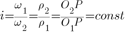
i.e. dot R normal crossings NN with a line of centers O 1 O 2 called engagement pole, should occupy a constant position on the line of centers O 1 O 2.
This implies a certain requirement for the tooth profiles of gears with a constant gear ratio.
The profiles of the teeth of both wheels must be such that the common normal to them at any point of contact passes through the engagement pole, which divides the line of the centers of the wheels into segments inversely proportional to the angular velocities.
Segments About 1 R and 0 2 R represent by radii r1 and r2 circles that have constant tangency at a point R. In this case, the formula can be written as follows: 
The equality following from the formula ω 1 r 1 =ω 2 r 2 circumferential speeds indicates that during the rotation of geared gears, circles of radii r1 and r2 roll over each other without slipping. These circles called initial, and the corresponding cylinders in a spur gear and cones in a bevel gear - initial cylinders and initial cones.
It follows from the above that the pitch circle passes through. through the pole of the engagement and rolls along the other initial circle without slipping. The pitch circle diameter is denoted d w and is called the initial diameter of the gear.
Of the variety of conjugated tooth profiles, the most common involute, which are distinguished by simplicity and convenience in the manufacture of teeth and allow the possibility of changing the center distance of the transmission within known boundaries without violating the correct engagement of the gears. Involute tooth profiles are formed by two symmetrical involutes.
An involute is a curve described by a point lying on a straight line (for example, a point AT in fig. 2b) rolling around the circumference without slipping. The straight line rolling around the circle is called the generating line, and the circle along which the generating line rolls is called the main circle.
The only parameter that determines the involute is the diameter of the main circle db(Fig. 2, b), since each given circle corresponds to only one definite involute. With the increase db the involute becomes flatter and at d b =∞ turns into a straight line. Therefore, in rack engagement, the profile of the rack tooth is straight. Since the involute cannot be inside the main circle, the involute tooth profile is performed only outside the main circle, and the part of the profile located inside it receives the corresponding shape during the manufacture of the teeth.
Terms, definitions and symbols related to geometry and kinematics gears various types with a constant gear ratio, established by GOST 16530-83, gear spur gears - GOST 16531-83 and gear bevel gears- GOST 19325-73. The main terms and designations of elements related to the geometry of gears are given in (Fig. 2).
Rice. 2It follows from the above that the generating line (general normal NN) is engagement line, i.e., the trajectory of the common point of contact of the mating teeth during its movement. Corner a tw between the line of engagement and a straight line perpendicular to the center line is called engagement angle.
The coaxial surface of the gear, which is the basis for determining the elements of the teeth and their dimensions, is called fissile. A circle centered on the axis of the gear, lying in the end section, is called concentric. The concentric circle belonging to the dividing surface is called pitch circle. The diameter of the dividing circle is called pitch diameter d of the gear. The cylinder of the spur gear corresponding to the pitch circle and the cone of the bevel gear are called dividing cylinder and dividing cone.
Coaxial surfaces separating the teeth from the body of the gear and limiting them from the side opposite to the body are called respectively depression surface and the surface of the tops of the gear teeth. A concentric circle belonging to a vertex surface is called vertex circumference, and the concentric circle belonging to the surface of the depressions - circumference of depressions. The diameter of the vertex circle is called diameter d a tooth tips, and the diameter of the circumference of the depressions - diameter d f tooth cavities.
The distance between the same profiles of adjacent teeth along the arc of the concentric circle of the gear is called circumferential tooth pitch P t(Fig. 3). There are pitch, initial and other circumferential pitches of the teeth corresponding to the pitch, initial and other concentric circles of the gear. For oblique (Fig. 3, a, b), chevron (Fig. 3, c) and curved teeth, except for the circumferential pitch pt there is also a normal tooth pitch p n, which is the shortest distance along the pitch or the same type of coaxial surface of the gear. Like circumferential pitches, there are dividing, initial and other normal pitches of the teeth; The central angle of the concentric circle of the gear, equal to 2π/z, or 360°/z, where z- the number of teeth of the gear, is called tooth pitch τ(Fig. 3, a).
Rice. 3The line of intersection of the lateral surface of the tooth with the dividing, initial or the same type of coaxial surface of the gear is called tooth line(Fig. 3, d). The acute angle between the line of the tooth intersecting at a given point and the line of intersection of the coaxial surface of the gear, to which this line of the tooth belongs, with a plane passing through its axis, is called angle of inclination of the tooth line or simply slope angle β(Fig. 3, b...d). There are dividing, initial and other angles of inclination corresponding to the dividing, initial and other lines of the tooth. The angle of inclination on the dividing cylinder is taken: for oblique teeth β=8...18°(rarely up to 25°); for chevron teeth β=25...40°.
From fig. 3, b, c 
The steps of the same name of the interlocking gears are equal to each other.
The angle of rotation of the gear wheel of the transmission from the position of the entry of the tooth into engagement to its disengagement is called overlap angle φ γ. The ratio of the overlap angle of a transmission gear to its angular pitch is called overlap ratio: ε γ =φ γ /τ.
For cylindrical helical, herringbone and other gears, the overlap ratio ε γ consists of the overlap coefficients of the end face ε α and axial ε β . Gear Angle cylindrical gear from the position of the engagement of the end profile of the tooth to the disengagement is called the angle of the end overlap φ α . End overlap coefficient ε α is called the ratio of the end overlap angle of the spur gear φ α to the pitch τ . The angle of rotation of the helical gear wheel, at which the common point of contact of the teeth moves along the tooth line of this gear from one of the ends that limit the working width of the crown to the other, is called the angle of axial overlap φ β . Axial overlap coefficient ε β is called the ratio of the angle of axial overlap of the gear of a helical spur gear φ β to the pitch τ . Overlap ratio for helical and other gears ε γ =ε α +ε β . Overlap ratio ε γ determines the average number of pairs of teeth that are simultaneously engaged. If a ε γ =1.6, then this means that 0.4 of the transmission time, one pair of teeth is engaged, and 0.6 of the transmission time, two pairs of teeth are engaged.
Since oblique, chevron and curved teeth are located obliquely, unlike straight teeth, they do not engage immediately along the entire length, but for some time and, therefore, the overlap coefficient of these teeth is greater than that of straight teeth. With an increase in the overlap coefficient, the smoothness of the engagement of the teeth increases, the dynamic loads on them decrease, and the noise that occurs during the operation of the transmission decreases. Therefore, in high-speed and highly loaded gears, instead of straight teeth, oblique, chevron and curved teeth are used. The overlap factor must always be greater than 1, since otherwise, during the operation of the gear train, there will be moments when the gear teeth will not engage and the gear will work with shocks. In spur gears, the overlap factor is always less than 2, usually ε γ =1,2,...1,8. In gears of helical, chevron and curved teeth, the overlap ratio ε γ >2.
Linear value, in π
times smaller than the circumferential pitch of the teeth is called circumferential tooth module m t and the linear value, in π
times smaller than the normal tooth pitch, is called the normal tooth module m n. In this way 
and 
For oblique, chevron and curved teeth, as follows from the formulas, 
For straight teeth m n =m t.
Since the dividing surface and the corresponding dividing circle are basic in determining the size of the teeth, the dimensions of the teeth of cylindrical gears are calculated according to the dividing normal modulus, which is called calculation module of the gear or simply module m. Module m- the main characteristic of the dimensions of gear and worm wheels. Involute gear modules are standardized by GOST 9563-60 (ST SEV 310-76). This International Standard applies to spur and bevel gears with straight teeth and specifies: for cylindrical wheels- values of normal modules, for conical - values of external circumferential dividing modules.
| 1st row | 1,0 | 1,25 | 1,5 | 2 | 2,5 | 3 | 4 | 5 | 6 | 8 | 10 | 12 | 16 | 20 | 25 |
|---|---|---|---|---|---|---|---|---|---|---|---|---|---|---|---|
| 1st row | 1,125 | 1,375 | 1,75 | 2,25 | 2,75 | 3,5 | 4,5 | 5,5 | 7 | 9 | 11 | 14 | 18 | 22 | 28 |
Gear Pitch Length πd=zp t =zp n / cos β, where pitch diameter
where z- number of gear teeth. For spur gear ![]()
It follows from the formulas that the module of the spur gear teeth
helical and chevron 
The distance between the axes of the gear wheels of a cylindrical transmission along the center line is called center distance:
where dw1 and dw2- initial diameters of gears and wheels; the plus sign refers to an external gear, and the minus sign to an internal gear.
Interaxal distance of a spur gear, equal to half the sum of the pitch diameters of the wheel d2 and gears d1 with external gearing or semi-difference with internal gearing, is called dividing center distance:
The width of the rim of a spur gear is determined by one of the formulas 
or  where ψ ba =b/a w- width factor ring gear by center distance, and ψbd =b/d 1- ratio of the width of the gear rim by the diameter of the gear: The numerical values of these coefficients are given when calculating the teeth of cylindrical gears.
Vertex diameters d a and hollows df teeth of spur gears (see Fig. 2): 
where h a- height of the tooth head;
h f- the height of the pedicle of the tooth.
For bevel gears, a section by the surface of an additional cone is taken as an end section, the axial line of which coincides with the axial line of the bevel gear, and the generatrix is perpendicular to the generatrix of the dividing cone (Fig. 4). The profiles of the teeth of bevel gears are close to the profiles of imaginary reduced cylindrical gears with initial radii equal to the lengths of the generatrix of additional cones.
Rice. fourThe ring gear of the bevel gear is limited to the outer and inner ends. Accordingly, for bevel gears, they distinguish (Fig. 4):
- pitch diameters - outer d e average. d m and etc.;
- initial diameters - outer d we, average dwm and etc.;
- tooth tip diameters - external dae, average d me and etc.;
- tooth root diameters - full dfe average d fm and etc.
The length of the segment of the generatrix of the dividing cone of the bevel gear from its top to the intersection with the generatrix of the dividing additional cone is called dividing cone distance or simply cone distance R. Distinguish external Re, internal R i and mean Rm dividing cone distances (Fig. 4).
For straight bevel gears as standard calculation module m teeth adopt external circumferential indexing module mte; the dimensions of the teeth, as well as the various diameters of the gears, are determined on the outer end, on which it is convenient to measure. For bevel gears with tangential (oblique) teeth, the external normal dividing module is taken as the standard calculation module of the teeth. mne. The dimensions of the pitch and initial diameters of bevel gears, as well as the dimensions of the teeth, are determined by the same formulas as for cylindrical gears.
External pitch diameters of vertices dae and hollows dfe teeth and outer pitch taper distance Re bevel gear (Fig. 4): 
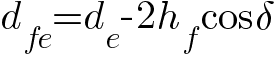
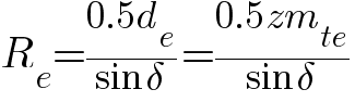
where δ
- the angle of the dividing cone, i.e. the angle between the axis of the bevel gear and the generatrix of its dividing cone.
Bevel gear ring width 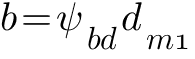
where dm1- dividing the average diameter of the gear, a ψ bd = b/d m1- ratio of the width of the gear rim according to the dividing average diameter of the gear, numerical values which are given when calculating the teeth of bevel gears.
Average pitch diameter d m bevel gear(fig. 4) 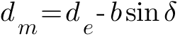
or m m z=mz-b sin δ, whence the average module of the teeth 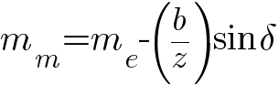
With an infinitely large diameter of the pitch circle, the gear wheel turns into a rack, and the involute tooth profile turns into a straight line, convenient for manufacturing and measuring. The possibility of engaging an involute gear with a rack is of great practical importance, since it allows the production of a gear-cutting tool in the form of a rack with straight-line teeth.
The acute angle in the selected section between the tangent to the tooth profile at a given point (Fig. 5, a) and the line of the shortest distance along the section surface from this point to the axis of the gear is called tooth profile angle or profile angle α. Distinguish dividing α , initial a w and other tooth profiles corresponding to points on the dividing, initial and coaxial surfaces of the same type.
Rice. 5The profiling of the teeth of the involute engagement and the tool for cutting them is carried out in accordance with the original contour, i.e., the contour of the teeth of the nominal initial rail in the section with a plane perpendicular to its dividing surface. The original contour of cylindrical involute gears with a module m≥1mm standardized by GOST 13755-81 (ST SEV 308-76), and bevel gears with straight teeth - GOST 13754-81. The profile of both contours (Fig. 5, b) is rectilinear, located at the same length on both sides of middle line a-a, along which the thickness of the tooth and the width of the cavity are equal. Distance R between the same profiles of adjacent teeth, measured parallel to the center line, is called reiki step. Half of the angle between the sides of the tool rack teeth is called profile angle α.
The ratio of the height of the head of the tooth to the module is called the coefficient of the height of the head of the tooth. h'a. The ratio of the value of the radial clearance to the module, denoted c', is called radial clearance factor.
According to GOST 13755-81 (ST SEV 308 - 76) and 13754-81 (ST SEV 516-77) parameters of the initial circuit:
profile angle α=20°;
tooth depth h ω =h′ m m=2m,
where h′ ω- coefficient of the depth of entry of the teeth;
reiki step p=πm;
head height factor h′ a =1;
radial clearance factor for spur gears c'=0.25(when processing teeth with a cutter and shavers up to c'=0.35 and before c'=0.4 when grinding teeth) and for bevel gears c'=0.2;
tooth radius at the base of spur gears p f =0.38m and bevel gears ρ t =0.2m.
In accordance with GOST 13755-81 (ST SEV 308-76) and 13754-81 (ST SEV 516-77), the dimensions of the teeth of normal involute engagement (Fig. 2 and 4): the height of the tooth head 
tooth root height 
tooth height 
For high-speed spur gears, in order to reduce shocks during the entry and exit of teeth from engagement and reduce noise, a contour with a straight cut should be used (Fig. 5, c).
The shape of the involute tooth profile at given angle profile and module depends on the number z teeth (Fig. 6, a). At infinite large numbers teeth, which corresponds to an infinitely large diameter of the pitch circle, the involute turns into a straight line. With a decrease in the number of teeth, the curvature of the involute profile increases and, accordingly, the thickness of the teeth at the base and at the top decreases. If number z teeth less than some limit value zmin, then when cutting teeth with a rack-type tool occurs (Fig. 6, a), as a result of which the bending strength of the teeth is significantly reduced. When cutting straight teeth of normal involute engagement with a rack-and-pinion tool, their minimum number, at which there is no undercutting, zmin=17. To eliminate undercutting of the teeth of normal involute gearing, offset gears. Compared to the normal involute gearing, the profiles of the teeth of the offset gearing are made by other sections of the involute of the same main circle that are more advantageous for a given transmission. The use of offset gears achieves not only an increase in the bending strength of the teeth, but also an increase in the bearing capacity in terms of contact strength, a decrease in tooth wear and the elimination of the phenomenon of jamming. In addition, offset engagement allows you to design a gear at a given center distance.
Rice. 6Offset gear teeth are made on the same machines and with the same standard tool as non-offset gear teeth. The difference is that when manufacturing offset gears, the tool is mounted with some offset in the radial direction. Accordingly, the blanks of wheels with an offset are made with a changed diameter.
Tool offset χ is determined by the formula ![]()
where x- displacement coefficient;
m- the module of the produced gear.
The bias factor is assumed to be positive ( x>0) when the tool moves away from the center of the workpiece, and negative ( X<0 ) when the tool moves towards the center of the workpiece.
(Fig. 6, b) shows the teeth made by the same tool, but with a different offset coefficient. It can be seen from the figure that the larger the value of the offset coefficient, the further the tooth profile is from the main circle. At the same time, the curvature of the involute profile decreases and the tooth thickens at the base, and sharpens at the top. As a result, the bending and contact strengths of the tooth are increased.
For a normal gear train (without offset) for the gear and wheel, the offset coefficient x=0, such a transfer is called zero.
There are two types of offset gears:
1) gear shift ratios x 1, wheels x2 and total x∑ satisfy the conditions x1 >0, x2<0
, |x 1 |=|x 2 | and x∑=x1+x2=0;
2) bias coefficients x 1, x2 and x∑ satisfy the condition x ∑ \u003d x 1 + x 2 ≠0(usually x1 >0, x 2 >0 and x ∑ >0).
In gears of the first type, the height of the teeth is constant, but the ratio of the heights of the head and root of the teeth changes and, accordingly, the diameters of the tops and bottoms of the teeth change. The height of the head and stem of the teeth, respectively (Fig. 7, a): 
The starting circles in gears of this type, as well as for gears without offset, coincide with the pitch circles, and the engagement angle does not change. The thickness of the gear teeth is increased by reducing the thickness of the wheel teeth. But the sum of the thicknesses along the pitch circle of a pair of interlocking teeth remains constant, equal to the pitch of the teeth. Therefore, gear transmission is carried out without changing the transmission center distance. The strength of the gear teeth increases while reducing the strength of the wheel teeth. With a large number of gear teeth and wheels, this transmission is not very effective. This transmission is used only with a small number of gear teeth and large gear ratios.
In gears of the second type, the sum of the thicknesses of the gear teeth and the wheel along the pitch circle more step teeth, so the pitch circles cannot touch; gears must be moved apart. As a result of this, the pitch circles will not coincide with the initial circles, the height of the teeth will decrease and the angle of engagement of the teeth will increase.
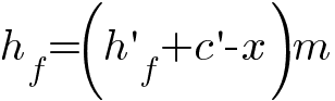
The dimensions of the teeth in this gear (Fig. 7, b): the height of the dividing head of the teeth 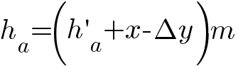
tooth pitch height 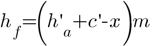
tooth height 
where Δy- equalization bias coefficient, which can be determined using the nomogram shown in (Fig. 8).
An example of using a nomogram.
Sum of gear and wheel teeth z c =64 tooth total displacement ratio of gear and wheel x∑=l.75. Determine equalization bias factor Δy. Value 1000 x ∑ /z c \u003d 1000 * 1.75 / 64 \u003d 27.4 according to the nomogram corresponds to the value 1000Δy/z c =3.69, hence Δy=3.69Z c /1000=3.69*64/1000=0.236.
The second type of offset gears has a number of advantages compared to the first type: increased strength of the teeth of both gears, the possibility of designing a gear with the desired center distance and for any combination of the numbers of gear and wheel teeth. Therefore, this type of transmission has a predominant application.
The limiting values of the bias factors are limited by the following factors:
- unacceptable cutting of teeth when cutting them with a tool;
- sharpening of the teeth, i.e., a decrease in their thickness along the circumference of the tops of the teeth below the permissible limit;
- manifestation of interference (mutual penetration) of the teeth during their operation;
- decrease in the overlap ratio.
In table. the recommended maximum bias coefficients are given x 1 and x 2 for spur gears with external gearing from the conditions of the greatest increase: contact strength of the teeth; bending strength (with equal strength of gear teeth and wheels made of the same material); wear resistance and resistance to jamming of teeth. In this table, the values of the coefficients x 1 and x2 are given assuming that the minimum thickness of the teeth around the circumference of the tips of the teeth s a ≥0.25m and overlap ratio ε γ ≥1.2. Recommendations for choosing the displacement coefficients of cylindrical involute gears are given in the appendices to GOST 16532-70.
As already noted, in gear drives without offset and gears with a shift of the first type, the dividing circle coincides with the initial circle (see Fig. 2, 4, 7, a), therefore, for these gears, the engagement angle 
initial gear diameter 
and center distance 
For these gears, the dividing center distance a cylindrical gear with external gearing (see Fig. 2 and 7, a) 
where z c \u003d z 1 + z 2- sum of gear teeth z1 and wheels z2.
It follows from the formula that the module of the teeth for the helical gear 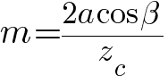
and for spur 
For a spur gear with a displacement of the second type (see Fig. 7, b), the center distance aw, engagement angle a tw and initial diameters of the leading dw1 and slave dw2 gear wheels: 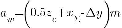

Pitch - a constant parameter of the gear, depending only on the module m and number of teeth z this wheel.
The initial circle is a kinematic concept, and a single wheel does not have such a circle.
We talk about pitch circles when we consider the wheels that are in engagement. As already noted, these circles are in contact at the pole of engagement and, as the gear wheels rotate, they roll over one another without slipping. When changing the center distance of a spur gear aw(see Fig. 7, b) the pitch circles do not change, and the diameters of the initial circles change in proportion to the change aw. Consequently, when changing the center distance of a spur gear, its pitch circles do not coincide with the initial circles. Detailed calculation geometric parameters cylindrical gears of involute external gearing are set out in GOST 16532-70, and bevel gears with straight teeth - in GOST 19624-74.
Having calculated all the dimensions of the gearing elements, we proceed to drawing the gearing.
|
Gear parameter |
d 1 |
d 2 |
din 1 |
din 2 |
S 2 |
aw | ||||||||
|
Scaled size, mm |
Example of calculation of gearing parameters
We draw the tooth profiles in the following sequence:
1. In the drawing, at an arbitrary angle, we set aside the line of centers O 1 O 2. The length of the line of centers is equal to the center distance O 1 O 2 =a w .
2. From the ends of the segment (line of centers), we set aside the initial circles d w1 and d w2. The initial circles d w1 and d w2 touch each other at the pole P.
3. Set aside and build the main circles d in 1 and d in 2.
4. Construction of the wheel involute 2.
4.1. Draw a tangent PA from the pole P to the base circle.
The segment AR (see Fig.) is divided into four equal parts (AB \u003d BC \u003d CD \u003d DP) and from point B we draw an arc of radius r \u003d BP until it intersects at point P 1 with the main circle; then AP 1 = AP.
4.2. After that, the segment AR is again divided into an arbitrary number of equal parts 15 ... 20 mm long (it is advisable to take the number of divisions even, for example 8). We also divide the arc AR 1 into such a number of equal parts (P 1 1 "= 1" 2" = 2" 3" = ...).
4.3. Points 1"; 2"; 3 "... we connect with the center O 2.
4.4. Through points 1"; 2"; 3 "... we draw perpendiculars to the corresponding radii O 2 1"; About 2 2 "; About 2 3" ....
On the perpendiculars (they touch the main circle), we set aside the segments 1"1""; 2"2""; 3"3""…, respectively, equal to the segments P1; P2; P3….
4.5. Connecting the points P 1 ; one""; 2""; 3""... smooth curve, we get part of the involute of the second wheel.
4.6. To continue constructing the tooth profile of the second wheel, we set aside and build the circles of the protrusions and cavities of the teeth of the second wheel. It should be noted that the radius of the circle of depressions can be greater than, equal to, or less than the radius r in the base circle. It depends on the number Z of the wheel teeth and on the displacement factor x. In our case, d в2 > d f2

4.6. To complete the construction of the involute of the second wheel, we introduce additional points 8 and 9. Points 8 and 9 are set aside counterclockwise from point A.
Using the method described above, we find points 8"" and 9"". We complete the construction of the involute of the second wheel.

4.7. The stem profile at the base of the tooth can be constructed in a simplified way. If rf< r в, то от основания эвольвенты до окружности впадин проводят радиальный отрезок, а затем у основания зуба делают закругление радиуса 0,2m. Упрощенное построение профиля ножки зуба не отражают истинного его очертания, а является только чертежным приемом.
5. We build the dividing circle of wheel 2 and get the point D of its intersection with the involute.
From point D we set aside on the dividing circle of wheel 2 (using the construction shown above) the arcs: to the left DE, to the right DF, each equal to the step length p. From the point E, D, F to the left we set aside (using the same construction) the arcs ER, DM, FH, each equal to the thickness S of the tooth along the dividing circle.
We divide the arcs DM, FH, ER in half at points T, Y, Q. We connect these points with the center O2, we obtain the axes of symmetry of the teeth. After that, we cut out a half-tooth template from hard paper, which we use to build the remaining teeth. It is obligatory to build three teeth - the first, the profile of which is built by points, and two, located to the right and left of the first.
Similarly, we build three teeth for another wheel.
6. When drawing tooth profiles, the following must be remembered: the presence of a gap on the active part of the engagement line between the profiles intersected by the engagement lines indicates an incorrect drawing.
Error examples:
The geometric calculation of the gear train is carried out on the condition that the number of teeth is given z 1 and z 2 , and the module of gears is known m(obtained from the calculation of the teeth for strength).
r= mz/2 - radius of the dividing circle(for zero wheels, the initial circles coincide with the pitch circles).
Dividing is called a circle for which the modulus has a standard value. The profile angle for the point of intersection of the lateral profile of the tooth with the pitch circle is 20 according to GOST. The pitch circle is the basis for measuring all geometrical parameters of the gear. The dividing and initial circles may coincide, but they have a fundamental difference. A single wheel has a pitch circle, but no pitch circles. The pitch circle characterizes one gear with which it is associated; the diameter of the pitch circle of this wheel is unchanged. The diameters of the pitch circles depend on the center-to-center distance; they can only be determined when the engagement of two wheels is considered.
p= m- step along the dividing circle(distance between the same points of two adjacent teeth; common for both wheels).
S=p/2= m/2 - tooth thickness by divides. circumference (for normal gear) .
r a = r + h a = mz/2+ fm= m/2(z+2) - radius of the circle of the protrusions,
where h a - height of the head of the tooth, h a = fm, where f – tooth head height coefficient, f=1 – for normal wheels; f=0.8 - for shortened wheels).
r f = r - h f = mz/2 – 1,25 m= m/2(z-2,5) - radius of the circle of depressions,
where h f - the height of the pedicle of the tooth, h f = fm+ c 0 m=1,25 m, where c 0 \u003d 0.25 is the coefficient of radial clearance.
h = h a + h f =2,25 m – tooth height (for any number of teeth for a given module, the height of the tooth will be the same, because does not depend on the number of teeth, but depends on the modulus).
r b = r cos = r cos 20 =0.94 r is the radius of the base circle, where =20 is the angle of the rail profile.
Basic parameters of normal gearing(cut without shifting the tool rail) z i 17: a = r 1 + r 2 =( m /2)( z 1 + z 2 ) - center distance.
Fig.17 Gear parameters
Undercutting, or interference, will take place when the actual line of engagement goes beyond the theoretical one. It depends on the number of teeth of the cut wheel (for z 17) .
x =(17- z)/17 - rack shift factor.
c = xm - the magnitude of the absolute shift of the rail.
a w =a cos / cos w =0.5m( z 1 +z 2 )cos20 / cos w .
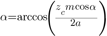
The value of the engagement angle in the assembly using the formula for the involute of the engagement angle:
Invw= inv20+2((x1+x2)/(z1+z2))tg20.
r i = m z i /2 - radii of pitch circles;
r bi = r i cos - radii of the main circles;
r w 1 = r b 1 / cos w ; r w 2 = a w - r w 1 - radii of initial circles;
r fi = r i -1,25 m + x i m are the radii of the circles of the depressions;
r ai = a w - r fi -0,25 m – vertex circle radii;
S i = p /2+2 x i m tg - pitch circle tooth thickness
h =2.25 m is the height of the tooth.
Gear Cutting Methods
Gears with an involute tooth profile are usually cut on special gear-cutting machines in two ways: 1) copying, 2) running.
Copy Method consists in the fact that the cutting edge of the cutter (disk or finger) has the shape of depressions between the teeth, and the lateral surface of the tooth turns out to be involute. In the manufacture of a gear wheel using this method, one cavity is cut in the workpiece in one pass of the cutter. Then the workpiece is rotated by an angular step and the next cavity is cut, and so on. This method is inefficient, requires a huge range of gear-cutting tools, and is mainly used for individual, small-scale or repair production.
Break-in method lies in the fact that the cutting tool (rail or cutter) and the workpiece are given the relative movement that two gear wheels, which are in the correct engagement.
To cut the teeth of involute wheels by running in, three types of tools are used: a tool rack, a worm cutter and a cutter. Cutting tool rail- the most accurate method of manufacturing involute wheels due to the simplicity of the tool profile. The disadvantages of the method are low productivity due to the existence of idling and the complexity of the machine, caused by the need to provide the tool with a complex flat movement.
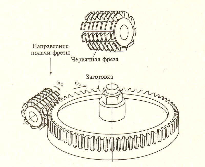
Such shortcomings are deprived of the method of cutting with a worm cutter, which is a cylinder with teeth arranged along helical lines; to form cutting edges and provide chip exit, the coils are crossed by longitudinal chip grooves. The cutting process is carried out continuously due to the rotational movement of the cutter and the workpiece. Due to the more complex shape of the tool, the accuracy of the wheels cut with a worm cutter is less than when cutting with a tool rack. However, both of these methods are not suitable for cutting wheels with teeth located on the inside of the rim, i.e. for internal gear wheels.
For cutting wheels of both external and internal gearing, tools in the form of a cutter are used. The cutter is an involute profile tool wheel, called the Fellow cutter after its inventor.

The design of all these tools is based on the contour of the generating (source) rail. To ensure interchangeability, i.e., the ability of mating parts to connect to each other without special fitting or selection, the dimensions of the original contour are regulated by GOST 13755-81. The theoretical initial contour is taken as the basis for the standard of shapes and sizes of gear teeth. On fig. a pair of original contours is shown. The base line of the original contour, along which the thickness of the tooth is equal to the width of the cavity, is called its dividing line. The dividing line divides the tooth in height into a dividing head and a dividing leg. The distance between the same profiles of adjacent teeth along the pitch or any other straight line parallel to it is called the pitch of the teeth. R original circuit.

All linear dimensions of the contour are given in fractions of the module.
The angle between the main profile of the tooth and the axis of symmetry of the tooth is called the angle of the main profile of the initial contour, or simply the angle of the profile of the initial contour. According to GOST 13755 - 81, the following values of the parameters of the initial circuit are set:
h a= 1.0; h f= 1.25; c* = 0.25; = 20°.
Source Generating Circuit- one that fills the cavities of the theoretical original contour, as a casting fills a mold, while maintaining a given radial clearance Withm between the top of the tooth and the bottom of the cavity, respectively, of the theoretical initial and initial generating contours. The radial clearance is made so that the surface of the cavity of the tool formed on the basis of the original generating contour does not participate in the process of cutting teeth. If the original generating contour is moved in a direction perpendicular to its plane, it will describe the surface of the original generating rack (tool rack).