GEARS
PLAN LECTIONS
1. General information.
2. Classification of gears.
3. Geometric parameters gear wheels.
4. Accuracy of parameter conversion.
5. Dynamic relationships in gears.
6. Wheel design. Materials and permissible stresses.
1. General information
Gear is a mechanism that, using gearing, transmits or converts motion with changes in angular velocities and moments. A gear train consists of wheels with teeth that mesh together to form a series of cam mechanisms operating in series.
Gears are used for converting and transmitting rotational movement between shafts with parallel, intersecting or intersecting axes, as well as to convert rotational motion into translational motion and vice versa.
Advantages of gears:
1. Constancy gear ratio i.
2. Reliability and durability.
3. Compactness.
4. Wide range of transmitted speeds.
5. Light pressure on the shafts.
6. High efficiency.
7. Easy to maintain.
Disadvantages of gears:
1. The need for high precision manufacturing and installation.
2. Noise when working at high speeds.
3. The impossibility of stepless regulation of the gear ratio
solutions i.
2. Classification of gears
Gears used in mechanical systems are varied. They are used to both reduce and increase angular velocity.
The classification of gear converter designs groups gears according to three criteria:
1. By type of tooth engagement. In technical devices, gears with external (Fig. 5.1,a), with internal (Fig. 5.1,b) and with rack and pinion (Fig. 5.1,c) gearing are used.
External gears are used to convert rotational motion with a change in direction of movement. The gear ratio varies between –0.1 and –10. Internal gearing is used when it is necessary to transform rotational motion while maintaining direction. Compared to external gearing, the transmission has smaller overall dimensions, a higher overlap coefficient and increased strength, but is more difficult to manufacture. Rack gear is used when converting rotational motion into translational motion and vice versa.

2. By relative position shaft axes transmissions are distinguished by cylindrical wheels with parallel shaft axes (Fig. 5.1, A ), conical wheels with intersecting axles (Fig. 5.2), wheels with intersecting axles (Fig. 5.3). Gears with bevel wheels have a smaller gear ratio (1/6 i 6), are more complex to manufacture and operate, and have additional axial loads. Helical wheels operate with increased slip, wear out faster, and have a low load capacity. These gears can provide different gear ratios with the same wheel diameters.
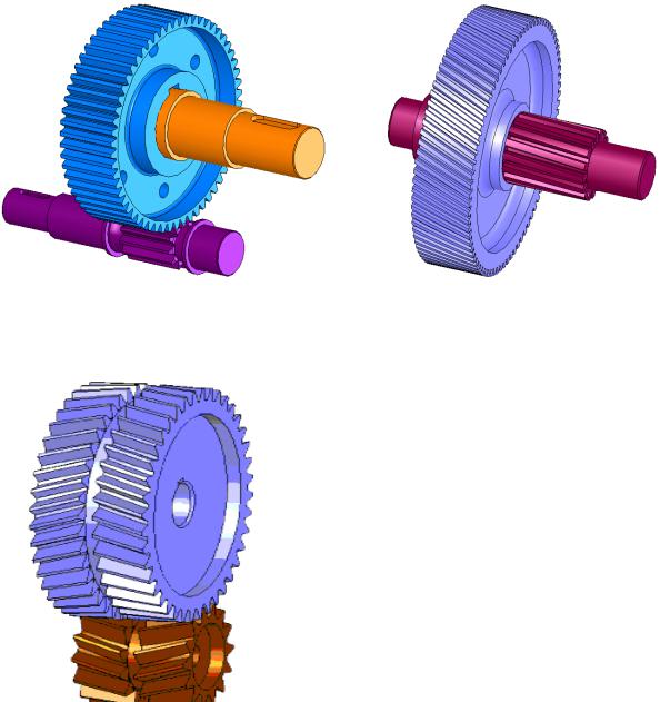
3. By the location of the teeth relative to the generatrix of the wheel rim
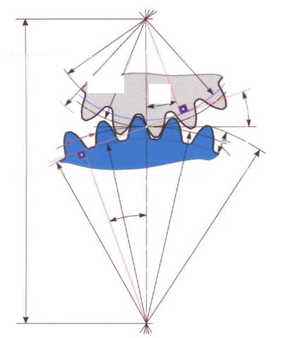
There are straight-tooth gears (Fig. 5.4, a), helical gears (Fig. 5.4, b), chevron gears (Fig. 5.5) and with circular teeth.
Helical gears have pain |
||||
smoother engagement, less |
||||
technologically | equivalent |
|||
straight-toothed, but in transmission they arise |
||||
additional | loads. |
|||
Double helical | counter |
|||
inclination of the teeth (chevron) transmission |
||||
cha has all the advantages of helical |
||||
and balanced axial forces. But |
||||
transmission is somewhat more difficult to manufacture |
||||
leniya and installation. Curvilinear |
||||
teeth are most often used in horse- |
||||
broadcasts | promotion |
|||
load capacity, | smoothness |
|||
work at high speeds. |
||||
3. Geometric parameters of gears
TO the main geometric parameters of gears (Fig. 5.6) include: tooth pitchР t, modulem (m =P t /), number of teeth Z, diameterd pitch circle, heighth a of the dividing head of the tooth, heighth f of the dividing leg of the tooth, diameters d a and d f of the circles of the peaks and valleys, width of the gear ring b.
df 1 | db 1 | |||
dw 1 (d1) | ||||
da 1 | ||||
df 2 | dw 2 (d2) | da 2 |
||
db 2 | ||||
Pitch circle diameter d =mZ. The pitch circle divides the wheel tooth into a pitch head and a pitch leg, the size ratio of which is determined by the relative position of the wheel blank and the tool during the cutting process.
At zero displacement of the original contour, the height of the dividing head and the leg of the gear tooth corresponds to those of the original contour, i.e.
ha =h a * m; hf =(h a * + c* ) m,
where h a * – tooth head height coefficient; c * – radial coefficient
For wheels with external teeth vertex circle diameter
da = d +2 ha =(Z +2 h a * ) m.
Diameter of the circle of the depressions
df = d –2 hf =(Z –2 h a * –2 c* ) m.
For m ≥ 1 mmh a * = 1,c * = 0.25,d a = (Z – 2.5)m.
For wheels with internal teeth The diameters of the circles of the peaks and valleys are as follows:
da = d –2 ha =(Z –2 h a * ) m;
df = d +2 hf =(Z +2 h a * +2 c* ) m.
For wheels cut with an offset, the diameters of the peaks and valleys are determined taking into account the value of the displacement coefficient according to more complex dependencies.
If two wheels, cut without displacement, are brought into engagement, then their pitch circles will touch, i.e., coincide with the initial circles. The engagement angle will be equal to angle profile of the initial contour, i.e. the initial legs and heads will coincide with the dividing legs and heads. The center distance will be equal to the pitch center distance, determined through the diameters of the pitch circles:
aw = a =(d1 + d2)/2 = m(Z1 + Z2)/2.
For wheels cut with an offset, there is a difference for the initial and pitch diameters, i.e.
d w 1 ≠d 1 ;d w 2 ≠d 2 ;a w ≠a ; αw = α.
4. Parameter conversion accuracy
IN During the operation of a gear transmission, a theoretically constant gear ratio undergoes continuous changes. These changes are caused by inevitable manufacturing errors in the size and shape of the teeth. The problem of manufacturing gears with low sensitivity to errors is solved in two directions:
a) the use of special types of profiles (for example, clock gear);
b) limitation of manufacturing errors.
IN Unlike simple parts such as shafts and bushings, gears are complex details, and errors in the execution of their individual elements not only affect the mating of two individual teeth, but also affect the dynamic and strength characteristics of the gear transmission as a whole, as well as the accuracy of transmission and transformation of rotational motion.
Errors of gears and gears, depending on their influence on the operational performance of the transmission, can be divided into four groups:
1) errors affecting kinematic accuracy, i.e. accuracy of transmission and transformation of rotational motion;
2) errors affecting the smooth operation of the gear train;
3) errors in the tooth contact pattern;
4) errors leading to changes in the side clearance and affecting the backlash of the transmission.
In each of these groups, complex errors can be identified that most fully characterize this group, and element-by-element, partially characterizing transmission performance indicators.
This division of errors into groups forms the basis of standards for tolerances and deviations of gears: GOST 1643–81 and GOST 9178–81.
To assess the kinematic accuracy of transmission, smoothness of rotation, characteristics of tooth contact and backlash, the standards under consideration establish 12 degrees of accuracy in the manufacture of gears
And transmission Degrees of accuracy in descending order are indicated by numbers 1–12. Accuracy degrees 1 and 2 according to GOST 1643–81 for m > 1 mm and according to GOST 9178–81 for 0.1 It is allowed to use gears and gears whose error groups may belong to different degrees of accuracy. However, a number of errors belonging to different groups in their influence on transmission accuracy are interrelated, therefore restrictions are set on combining accuracy standards. Thus, smoothness standards can be no more than two degrees more precise or one degree coarser than kinematic accuracy standards, and tooth contact standards can be assigned to any degree more accurate than smoothness standards. Combining accuracy standards allows the designer to create the most economical gears, while choosing such degrees of accuracy for individual displays. tel that meet the operational requirements for a given transmission, without increasing the cost of manufacturing the transmission. The choice of degrees of accuracy depends on the purpose, area of application of the wheels and the peripheral speed of rotation of the teeth. Let us consider in more detail the errors of gears and gears that affect their quality. 5. Dynamic relationships in gears Gear drives transform not only motion parameters, but also load parameters. In the process of converting mechanical energy, part of the power P tr supplied to the input of the converter is spent on overcoming rolling and sliding friction in kinematic pairs of gears. As a result, the output power decreases. To estimate the loss power, the concept of efficiency is used, defined as the ratio of the power at the output of the converter to the power supplied to its input, i.e. η = P out / P in . If a gear train transforms rotational motion, then, accordingly, the input and output powers can be determined as Let us denote ωout /ωin through i , and the value T out /T in through i m , which we will call the torque transfer ratio. Then expression (5.3) will take the form η = i m. The value of η ranges from 0.94–0.96 and depends on the type of transmission and the transmitted load. For a cylindrical gear transmission, the efficiency can be determined from the relationship η = 1 – cf π(1/Z 1 + 1/Z 2 ), where c is a correction factor that takes into account the decrease in efficiency with a decrease in transmitted power; 20T out 292mZ 2 20T out 17.4mZ 2 where Tout is the output torque, H mm; f is the friction coefficient between the teeth. To determine the actual forces on the gear teeth, consider Rome load conversion process (Fig. 5.7). Let the driving input moment T 1 be applied to the drive gear1 with the diameter of the initial circle d w l , and the resistance moment T 2 of the driven wheel2 be directed in the direction opposite to the rotation of the wheel. In an involute gearing, the point of contact is always on a line that is the common normal to the contacting profiles. Consequently, the pressure force of the tooth F of the driving wheel on the tooth of the driven wheel will be directed normally. Let us transfer the force along the line of action to the engagement pole P and decompose it into two components. Ft' Ft' The tangent component F t is called circumferential force. She performs useful work, overcoming the moment of resistance T and driving the wheels. Its value can be calculated using the formula F t = 2T /d w . The vertical component is called radial force and is denoted by F r. This force does not do any work; it only creates additional load on the shafts and transmission supports. When determining the magnitude of both forces, the friction forces between the teeth can be neglected. In this case, the following dependencies exist between the total pressure force of the teeth and its components: F n =F t /(cos α cos); F r =F t tg α/ cos , where α is the engagement angle. Cylindrical engagement spur gears has a number of significant dynamic disadvantages: limited overlap coefficient values, significant noise and shocks at high speeds. To reduce the dimensions of the transmission and reduce the smoothness of operation, the spur gear is often replaced with a helical gear, the side profiles of the teeth of which are involute helical surfaces. In helical gears, the total force F is directed perpendicular to the tooth. Let us decompose this force into two components: F t – circumferential force of the wheel and F a – axial force directed along the geometric axis of the wheel; F a =F t tg β, where is the angle of inclination of the tooth. Thus, in a helical gear, unlike a spur gear, three mutually perpendicular forces F a , F r , F t act, of which only F t performs useful work. 6. Wheel design. Materials and permissible stresses Wheel design. When studying the principles of designing gears, the main goal is to master the methodology for determining the shape and basic parameters of wheels according to the conditions of performance and operation. Achieving this goal is possible by solving the following tasks: a) selection of optimal wheel materials and determination of acceptable mechanical characteristics; b) calculation of wheel sizes according to the conditions of contact and bending strength; c) development of gear design. Gear drives are typical converters for which quite a lot of well-founded optimal design options have been developed. A general diagram of the design of a gear wheel can be presented as a combination of three main structural elements: a ring gear, a hub and a central disk (Fig. 5.9). The shape and dimensions of the gear are determined depending on the number of teeth, module, shaft diameter, as well as the material and manufacturing technology of the wheels. In Fig. Figure 5.8 shows examples of gear designs for mechanisms. It is recommended to take wheel sizes in accordance with the instructions of GOST 13733–77. By clicking on the "Download archive" button, you will download the file you need completely free of charge. To download an archive with a document, enter a five-digit number in the field below and click the "Download archive" button Calculation and standardization of gear accuracy. Selecting gear precision levels. Selecting the type of mating, transmission wheel teeth. Selection of indicators for gear control. Calculation and standardization of accuracy of smooth cylindrical joints. test, added 08/28/2010 Gear mechanisms in which movement between links is transmitted by sequential engagement of teeth. Classification of gears. Elements of transmission gearing theory. Geometric calculation of involute spur gears. Gear designs. presentation, added 02/24/2014 Gear geometry. Cylindrical, bevel, worm, spur, chevron wheels. Basic parameters of the rack. Geometric dimensions of gears. Rows of gears. Constructing a speed picture for a planetary gear mechanism. presentation, added 09/04/2013 Study of the theoretical foundations of cutting gears using the rack rolling method. Construction of wheel profiles using the device. Milling the teeth of a cylindrical wheel. Tooth shape depending on displacement. The position of the rack relative to the wheel. laboratory work, added 06/04/2009 Selecting an electric motor: the procedure for calculating the required power and other parameters. Justification for the choice of gear transmission: selection of materials, calculation of permissible stress and bending, sizes of wheel and gear teeth, test calculation of gearbox shafts. course work, added 01/11/2013 Geometric parameters of bevel gears. Forces in bevel gears. Gear ratio is the ratio of the number of teeth of the driven gear to the drive gear. Reducing a spur bevel gear to an equivalent spur gear. abstract, added 03/15/2014 Design features and parameters of cylindrical and bevel gears. Mounted ring gear. Sliding of teeth during transmission operation. Forces in a spur gear. Performance criteria for closed gears. presentation, added 08/25/2013
Lecture 6 6.5. Basic geometric parameters of straight teeth cylindrical gears In gears, it is customary to call the smaller gear gear. The module m is taken as the main gearing parameter - a value proportional to the pitch P pitch diameter, http://pandia.ru/text/79/022/images/image002_53.gif" width="373" height="371 src= "> Rice. 6.6. Geometric parameters of cylindrical gears For spur gears manufactured without offset, the pitch diameter is equal to the product The diameter of the tops of the gear wheels is determined by the sum , The diameter of the depressions is calculated by the difference The center distance is determined by half the sum of the gear diameters The width of the gear is where ya is the width coefficient, which is selected depending on the location of the gears relative to the supports and the hardness of the working surfaces of the teeth. The width of the gear is taken to be 1.12 times greater than the width of the wheel 6.6. Features of the geometry of helical gears U helical wheels the teeth are inclined at an angle 3 to the generatrix of the dividing cylinder. Cutting helical wheels can be done with a spur rack, as when cutting spur wheels. The inclination of the tooth is obtained by rotating the tool relative to the workpiece generatrix at an angle b. The calculation of the geometric parameters of helical gears is carried out using the same formulas as for spur gears, substituting the end mt module instead of the normal m. The end module is related to the normal one by the following relationship: Then the diameter of the helical gear can be represented in the following form The section of the dividing cylinder normal to the tooth line is an ellipse (Fig. 6.7) with semi-axes c = 0.5×d and e = 0.5×d / cosb. The radius and diameter of curvature of this ellipse at the meshing pole are http://pandia.ru/text/79/022/images/image018_7.gif" width="75" height="48 src=">.gif" width="84" height="48 src=">, (6.22) where a is the tooth profile angle, a = 200 when cutting teeth without tool displacement. http://pandia.ru/text/79/022/images/image018_7.gif" width="75" height="48">. (6.23) The axial force directed along the axis is OZ Fig.6.9. Scheme of forces in engagement of helical wheels The geometric sum of the circumferential Ft and axial Fa forces is the force Fta directed along the normal to the tooth at an angle to the generatrix of the cylinder b, can be calculated from the relation Then the radial force directed along the OY axis has the form The force normal to the tooth surface is

![]()
Classification of gears according to the shape of the teeth profile, their type, and the relative position of the shaft axes. Basic elements of a gear wheel. Calculation of the basic geometric parameters of a cylindrical gear transmission. Measuring the diameter of the tops of the wheel teeth.
Before downloading this file, think about those good abstracts, tests, term papers, dissertations, articles and other documents that are lying unclaimed on your computer. This is your work, it should participate in the development of society and benefit people. Find these works and submit them to the knowledge base.
We and all students, graduate students, young scientists who use the knowledge base in their studies and work will be very grateful to you.Similar documents
![]() . (6.13)
. (6.13)![]() ,
, ![]() . (6.14)
. (6.14) . (6.19)
 , http://pandia.ru/text/79/022/images/image016_9.gif" width="236" height="53">. (6.21)
http://pandia.ru/text/79/022/images/image025_2.gif" width="453" height="325">
 . (6.26)
 . (6.27)
Calculation of gears for strength begins with determining the design load
http://pandia.ru/text/79/022/images/image030_1.gif" width="81" height="28 src=">. (6.28)
The strength of the teeth is influenced by factors that are taken into account by the coefficients. It is convenient to present the load factor K as a product of partial coefficients that take into account individual factors
![]() . (6.29)
. (6.29)
The coefficient of load distribution between the teeth Ka takes into account the manufacturing errors of double-pair gears. Physical meaning is as follows: during the meshing process without load, only one pair of teeth is in contact, the second pair of teeth does not touch due to manufacturing errors. When loaded, elastic deformation of the first pair of teeth occurs and the second pair also comes into contact, but it takes less load. The load distribution coefficient between the teeth for helical gears with double-pair gearing is determined depending on the degree of manufacturing accuracy, and for spur gears with single-pair gearing, Ka = 1.
The concentration coefficient Kb takes into account the load distribution along the tooth. Due to the deformation of the shafts, the teeth of the wheels without load contact not along a line, but at a point. Under load, contact, due to elastic deformation of the teeth, occurs along a line along the tooth, but at the point of initial contact the stress will be higher. The load concentration coefficient depends on the location of the gears relative to the supports, the width of the rim relative to the diameter of the wheel and the hardness of the working surfaces of the teeth.
Errors in cutting teeth lead to variability in the instantaneous gear ratio, which causes the appearance of angular accelerations of the sprocket, and therefore dynamic loads. This additional load is taken into account
dynamic coefficient KV, which is determined depending on the degree of precision in wheel manufacturing, surface hardness and peripheral speed of the wheels.
1. Spur gears. Let us first consider the simplest cylindrical gear transmission - spur gear (Fig. 5). The part of the gear on which the teeth are located is called the ring; The part that fits onto the shaft is called the hub. A dividing circle with a diameter d divides the tooth in height into two parts - a head with a height of ha and a stem with a height of hfi, while the height of the tooth is h = ha + hf. The distance P between the same profiles of adjacent teeth, measured along the arc of the pitch circle, is called circumferential dividing step teeth; it consists of the circumferential thickness of the tooth S and the width of the cavity e. The value m, which has the dimension of length and is equal to m = P/n, (Fig. 5) called the circumferential divisor module, or simply the module. Modulus is one of the main parameters of a gear; wheels that mesh with each other must have the same module. The modules are standardized and their meanings can be found in Part 5 of the textbook. In mechanical engineering, module values from 1 to 14 mm are most often used. All main parameters of gears are expressed through the module. Tooth pitch P = pt; pitch circle diameter d = mz,
(Fig.5) Fig. 5. Straight tooth spur gear:
1 - circle of the tops of the teeth; 2 - dividing circle; 3 - circle of depressions
where z is the number of teeth of the wheel whose pitch circle is being determined.
In the manufacture of gears, the gear engagement is considered as the initial
sa with a gear rack. In this case, the rack is called the nominal original rack, and the contour of its teeth is called the original contour. In accordance with the standard initial contour for cylindrical gears (Fig. 6), the height of the tooth head ha = = m, the height of the tooth root h/ = m + c = 1.25m, where c is the radial clearance; the profile of the initial contour within the entry depth hd ~ = 2t is straight; at the base of the tooth there is a radius of curvature r = 0.25t. Based on the above: the height of the teeth of cylindrical wheels  Rice. 6. Standard initial contour for spur gearsd =2.25m; (Fig. 6) diameter of the tooth tips da = d + 2ha = mz-i = m(z (Fig. 7) n diameter of the teeth df = d-2hf = mz-2- (Fig. 8) Center-to-center pitch distance of the gear drive (Fig. 7) .9)
The "-" sign corresponds to internal gearing. If the center distance differs from the pitch distance, which also occurs, then it is designated aw.
The distance between the ends of the teeth b (tooth length) is called the width of the crown (Fig. 8.5). During the operation of a spur gear, a pair of teeth engages immediately along the entire length of the contact (theoretically, the contact of the teeth occurs along a line), which is accompanied by the teeth hitting each other. But since the other pair of teeth, which was already in mesh, has not yet left it, two pairs of teeth are in mesh. Then, also simultaneously, this other pair disengages, and only one pair of teeth remains in contact. All this is accompanied by changes in tooth deformations, which are stronger with single-pair gearing than with double-pair gearing, vibrations and other dynamic loads. As already mentioned, the duration of the transmission being in single- and double-pair engagements depends on the overlap coefficient e.
The spur gear has only an end overlap. The end overlap coefficient ea (different from the overlap coefficient ey by the index) is equal to the ratio of the end overlap angle fa to the angular step t:
£«=Fa/t. (Fig.10)
For spur gears, cpa corresponds to (pY in Fig. 8.3, and the mechanical overlap coefficient for these gears is recommended to be ei > 1.2.
The standard provides 12 degrees of accuracy for cylindrical gears, with the first being the highest. For each degree of accuracy, standards are established for kinematic accuracy, smooth operation and contact of teeth and gears. In mechanical engineering, general-purpose gears are manufactured to 6-9 degrees of accuracy, which are used for spur gears at peripheral speeds of up to 15...2 m/s, respectively.
The most common in mechanical engineering are helical gears (Fig. 7). Helical gears with parallel axes have the opposite direction of the teeth of the driving and driven wheels (Fig. 7, a) and, like spur gears, belong to cylindrical gears. Let us note for comparison that helical-wheel drives (see Fig. 2.12), the axes of which are crossed and the wheels of which are similar to helical ones, have the same directions. 

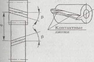 Fig.7. Parameters of cylindrical helical gears and gears: a - direction of teeth; b - cross-section of teeth with a normal
alignment of the teeth of both wheels; the initial contact of the working surfaces of the teeth occurs not along a line, but at a point. If you imagine the line of intersection of the side surface of a helical gear tooth with a cylindrical pitch surface, you will get a helical line of constant pitch. In helical gears, this line (tooth line) can have a right or left direction, like a helical thread line. The angle of inclination of the tooth line is indicated by the letter p. As can be seen from Fig. 7, a, in helical gears the contact lines are located obliquely with respect to the tooth line, therefore, unlike straight teeth, oblique teeth do not engage immediately along the entire length, but gradually. The overlap angle of a helical gear consists of the face and axial overlap angles, and the overlap coefficient eth of the helical gear consists of the coefficients of the face ea and axial overlap ep:
eg = £ « + ep > 2. (8.Ts) Unlike a spur gear, a helical gear does not have a period of one-pair engagement. Therefore, these gears are significantly more durable and smooth in operation. For example, for helical wheels of 6-9 degrees of accuracy, peripheral speeds of 30...4 m/s are permissible, respectively. Since helical gears are processed with the same gear-cutting tools as spur gears, the standard parameters of the wheels are set in the normal section NN to the tooth (Fig. 8.7, b). For helical gears, three modules are used: normal - t„ = P„/p, circumferential - t, = P,/p and axial - tx = Px/p, where P„, P, and Px are the normal pitch, respectively, measured by pitch circle; circumferential pitch measured along the arc of the pitch circle in the end section; axial pitch measured along the generatrix of the dividing cylinder.
As follows from Fig. 7, b:
P, =P„/soBr; t, =mfl/cosp.
All sizes of helical gear teeth are determined by the normal modulus TP:
h = ha + hf = tn + 1.25t„ = 2.25t„, and the diameter of the pitch circle is based on the circumferential modulus:
d = m,z- mnz/cosp. (8. I) Other sizes of helical gears are determined by the formulas: diameter of the tooth tips da =d + 2ha =d + 2mn; diameter of the depressions df =d-2hf =d-2.5mn; center distance
a = m,(z + Z2)/2 = mri(zl + ^2)/(2cosp). Axial overlap coefficient of helical gear
where b is the width of the crown; Px is the axial pitch. If e is an integer, then the total length of the contact lines will remain constant all the time, which has a positive effect on the operation of the gear, since the load on the teeth during the meshing process remains constant (for comparison, see what was said above about the loads on the teeth spur gears). Total length of helical gear contact lines
1g = £ea/cosp. A disadvantage of helical gears can be considered the axial force Fa arising during gear operation, caused by the angle p and equal to
Fa = Ft*b where F; = 2Tjd, here T is the transmitted torque, d is the diameter of the pitch circle. This drawback is eliminated in chevron gears, the width of which consists of sections with teeth with opposite angles of inclination (Fig. 8).
IN chevron wheels axial forces Fa are mutually balanced and are not transmitted to the shaft supports. In Fig. .8, a shows a chevron gear with a track of width a in the middle of the crown; It’s more technologically advanced to cut the teeth with a milling cutter, but the result is a wheel
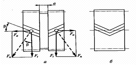 Fig.8. Cylindrical chevron gear: a - with a track in the middle of the wheel; b - without track
large thickness. In Fig. 8, £ shows a chevron wheel without a track, the manufacture of which is difficult.
Since the axial forces in chevron wheels are balanced, the angles of inclination of the teeth p can be increased from 20°, their largest value for helical wheels in general mechanical engineering, to 40... 45°. At the same time, the smoothness of operation and its load capacity increase significantly. However, chevron wheels are labor-intensive to manufacture and expensive, and require specific fixation in supports. Only one wheel is fixed in the axial direction, and the second wheel mated to it must move freely in this direction, since the axial fixation here occurs along the teeth of the chevron wheel.
The principle of operation of a gear transmission is based on the meshing of a pair of gear wheels. Classification of gears is carried out according to the following criteria: according to the location of the shaft axes:
- gears with parallel axes (cylindrical)
- gears with intersecting axes (bevel)
- gears with intersecting axes (cylindrical screw)
by tooth arrangement:
- straight teeth;
- helical
- according to the shape of the teeth profile.
- involute;
- circular.
Cylindrical gears. They are made with cylindrical wheels of external internal gearing; in addition, transmissions are used between the gear wheel and the rack. Advantages:
- small dimensions;
- high load capacity;
- greater durability and reliability;
- high efficiency;
- constancy of the gear ratio;
- possibility of application in a wide range of speeds, powers and gear ratios.
Flaws:
- noise at high speeds;
- increased requirements for production;
- high rigidity does not allow to compensate for dynamic loads.
The smaller of a pair of gears is called a pinion.
and the larger one is a wheel.
The term "gear" is a general one.
The gear parameters are assigned index 1,
and wheel parameters - 2.
In addition, there are indices related to: w - to the initial surface or circle;
b - to the main surface or circle;
a - to the surface or circumference of the tops and heads of the teeth;
f- to the surface or circumference of the teeth's cavities and legs.
Parameters related to the pitch surface or circle are not assigned an additional index.
51. Threads.(not all)
Calculation of thread strength
The main types of destruction of fastening threads are cut of turns. In accordance with this, the main performance and design criteria for fastening threads are the strength associated with shear stresses τ,
Conditions for thread strength based on shear stress
τ =F/(π d 1 H K K m)≤[τ ] for screw,
τ =F/(π d H K K m) ≤ : [τ ] for nut
Where: d and d 1 outer and inner thread diameters;
N- the height of the nut or the depth of screwing the screw into the part;
K=ab/p or K=se/r- thread completeness coefficient;
K t- load unevenness coefficient along thread turns.
If the materials of the screw and nut are the same, then only the screw thread is calculated from the shear stresses, since d 1
Welded joints, Welding methods. Calculation of the strength of welded joints.
The types of welding used in apparatus construction are as follows: Manual arc; arc automatic; in a protective gas environment; atomic hydrogen; electroslag (for joining body parts); contact; acetylene-oxygen; explosion; cold press; induction; plasma beam; ultrasonic The strength of a welded joint depends on the following main factors: the quality of the base material, determined by its ability to weld, the perfection of the welding process; connection designs; welding method; the nature of the existing loads (constant or variable). (LABORATORY)
Classification of bearings.
Bearings serve as supports for shafts and rotating axles. They perceive radial and axial loads applied to the shaft and maintain the specified position of the shaft rotation axis. Bearings are classified according to the type of friction and the load they can bear. Based on the type of friction, they are distinguished: sliding bearings, in which the supporting section of the shaft slides along the surface of the bearing; rolling bearings in which sliding friction is replaced by rolling friction of balls or rollers. Bearings are distinguished according to the perceived load: radial - accept radial loads; persistent - perceive axial loads; radial thrust - perceive radial and axial loads. The supporting section of the shaft is called a journal. The shape of the working surface of the sliding bearing, as well as the shape of the shaft journal, can be cylindrical, flat, conical or spherical. A journal that transmits radial load is called a tenon if it is located at the end of the shaft, and a journal if it is located in the middle of the shaft. The axle that transmits the axial load is called the heel, and the bearing support is called the thrust bearing. Thrust bearings usually work in tandem with radial bearings.