4. Main types mechanical gears.
mechanical transmission called a device for transmitting mechanical movement from the engine to the executive bodies of the machine. It can be carried out with a change in the value and direction of the speed of movement, with the transformation of the type of movement. The need to use such devices is due to the inexpediency, and sometimes the impossibility of direct connection of the working body of the machine with the motor shaft. Mechanisms of rotational movement allow for continuous and uniform movement with the least energy loss to overcome friction and the least inertial loads.
Mechanical transmissions of rotational motion are divided into:
According to the method of transferring movement from the leading link to the slave link for gears friction(friction, belt) and engagement(chain, gear, worm);
According to the ratio of the speeds of the driving and driven links on slowing down(reducers) and accelerating(animators);
According to the mutual arrangement of the axes of the driving and driven shafts for gears with parallel, intersecting And intersecting shaft axes.
gears
gear train a three-link mechanism is called, in which two moving links are gears, or a wheel and a rack with teeth that form a rotational or translational pair with a fixed link (body).
The gear train consists of two wheels, through which they interlock with each other. A gear with fewer teeth is called gear, With a large number teeth - wheel.
planetary gears
planetary transmissions containing gears with moving axles are called. The transmission consists of a central wheel with external teeth, a central wheel with internal teeth, a carrier and satellites. Satellites rotate around their axes and together with the axis around the central wheel, i.e. move like planets.
Worm gears
Worm-gear used to transfer rotation from one shaft to another when the axes of the shafts intersect. The crossing angle in most cases is 90º. The most common worm gear consists of the so-called Archimedean worm, i.e. screw having a trapezoidal thread with a profile angle in the axial section equal to the double engagement angle (2 α = 40), and a worm wheel.
Wave mechanical transmissions
Wave transmission is based on the principle of transformation of motion parameters due to wave deformation of the flexible link of the mechanism.
Wave gears are a type of planetary gears in which one of the wheels is flexible.
Friction gears
Gears, the operation of which is based on the use of friction forces arising between the working surfaces of two bodies of rotation pressed against each other, are called friction gears.
Belt drives
Belting consists of two pulleys mounted on shafts and a belt covering them. The belt is put on pulleys with a certain tension, providing friction between the belt and the pulleys, sufficient to transfer power from the drive pulley to the driven one.
Depending on the shape cross section belts are distinguished: flat-belt, V-belt and round-belt
chain drives
chain drive consists of two wheels with teeth (asterisks) and a chain covering them. The most common gears are bush-roller chain and toothed chain. Chain gears are used to transfer medium power (not more than 150 kW) between parallel shafts in cases where the center distances are large for gears.
Transmission screw-nut
Transmission screw-nut serves to convert rotational motion into translational. The widespread use of such gears is determined by the fact that with a simple and compact design, it is possible to carry out slow and accurate movements.
In the aircraft industry, the screw-nut transmission is used in aircraft control mechanisms: to move the take-off and landing flaps, to control trimmers, rotary stabilizers, etc.
The advantages of transmission include simplicity and compact design, big win in force, accuracy of movements.
The disadvantage of the transmission is a large friction loss and the associated low efficiency.
Cam mechanisms
Cam mechanisms(Fig. 2.26) in terms of breadth of application they are second only to gears. They are used in machine tools and presses, internal combustion engines, machines for the textile, food and printing industries. In these machines, they perform the functions of approaching and retracting tools, feeding and clamping material in machines, pushing, turning, moving products, etc.
Types of mechanical gears and transmission mechanisms
Rotational motion in machines is transmitted by friction, gear, belt, chain and worm gears. We will arbitrarily call a pair that performs rotary motion, wheels. The wheel from which the rotation is transmitted is called the driving wheel, and the wheel receiving the movement is called the driven wheel.
Any rotational movement can be measured in revolutions per minute. Knowing the RPM of the drive wheel, we can determine the RPM of the driven wheel. The number of revolutions of the driven wheel depends on the ratio of the diameters of the connected wheels. If the diameters of both wheels are the same, then the wheels will spin at the same speed. If the diameter of the driven wheel is larger than the driving wheel, then the driven wheel will spin more slowly, and vice versa, if its diameter is smaller, it will make more revolutions. The number of revolutions of the driven wheel so many times less than number revolutions of the drive, how many times its diameter is greater than the diameter of the drive wheel.
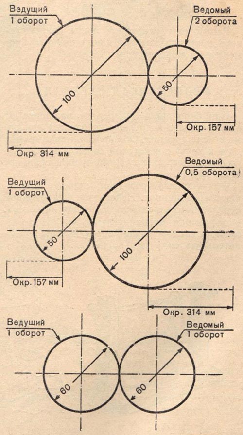
The dependence of the number of revolutions on the diameters of the wheels.
In engineering, when designing machines, it is often necessary to determine the diameters of the wheels and their number of revolutions. These calculations can be done on the basis of simple arithmetic proportions. For example, if we conventionally denote the diameter of the drive wheel as D 1, the diameter of the driven through D 2, the number of revolutions of the drive wheel through n 1, the number of revolutions of the driven wheel through n 2, then all these quantities are expressed by a simple relation:
D 2 / D 1 \u003d n 1 / n 2
If we know three quantities, then by substituting them into the formula, we can easily find the fourth, unknown quantity.
In technology, one often has to use the expressions: "gear ratio" and " gear ratio". The gear ratio is the ratio of the number of revolutions of the drive wheel (shaft) to the number of revolutions of the driven, and the gear ratio is the ratio between the numbers of revolutions of the wheels, regardless of which one is the drive one. Mathematically, the gear ratio is written as follows:
n 1 / n 2 = i or D 2 / D 1 = i
Where i- gear ratio. The gear ratio is an abstract value and has no dimension. The gear ratio can be anything - both integer and fractional.
friction gear
With frictional transmission, the rotation from one wheel to another is transmitted using friction force. Both wheels are pressed against each other with some force and, due to the friction between them, rotate one another. Disadvantage of friction gear: a large force pressing on the wheels, causing additional friction, and therefore requiring additional force to rotate. In addition, the wheels during rotation, no matter how they are pressed against each other, give slippage. Therefore, where an exact ratio of the number of revolutions of the wheels is required, the friction transmission does not justify itself.
Advantages of friction transmission:
Easy to manufacture rolling elements;
Uniform rotation and quiet operation;
Possibility of stepless speed control and on/off transmission on the go;
Due to the possibility of slipping, the transmission has safety properties.
Disadvantages of friction gear:
Slippage leading to inconsistent gear ratio and loss of energy;
The need for clamping.
Application of friction gear:
In mechanical engineering, stepless friction gears are most often used for stepless speed control.
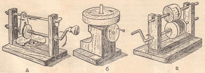
Friction gears:
a - frontal gear, b - angular gear, c - cylindrical gear.
IN homemade devices friction gear can be widely used. Cylindrical and frontal gears are especially acceptable. Gear wheels can be made of wood. For better grip, the working surfaces of the wheels should be "sheathed" with a layer of soft rubber 2-3 mm thick. Rubber can be either nailed with small cloves or glued with glue.
Gear
In gears, the rotation from one wheel to another is transmitted by means of teeth. Gear wheels rotate much easier than friction wheels. This is explained by the fact that here pressing the wheel on the wheel is not required at all. For proper engagement and easy operation of the wheels, the tooth profile is made along a certain curve, called an involute.
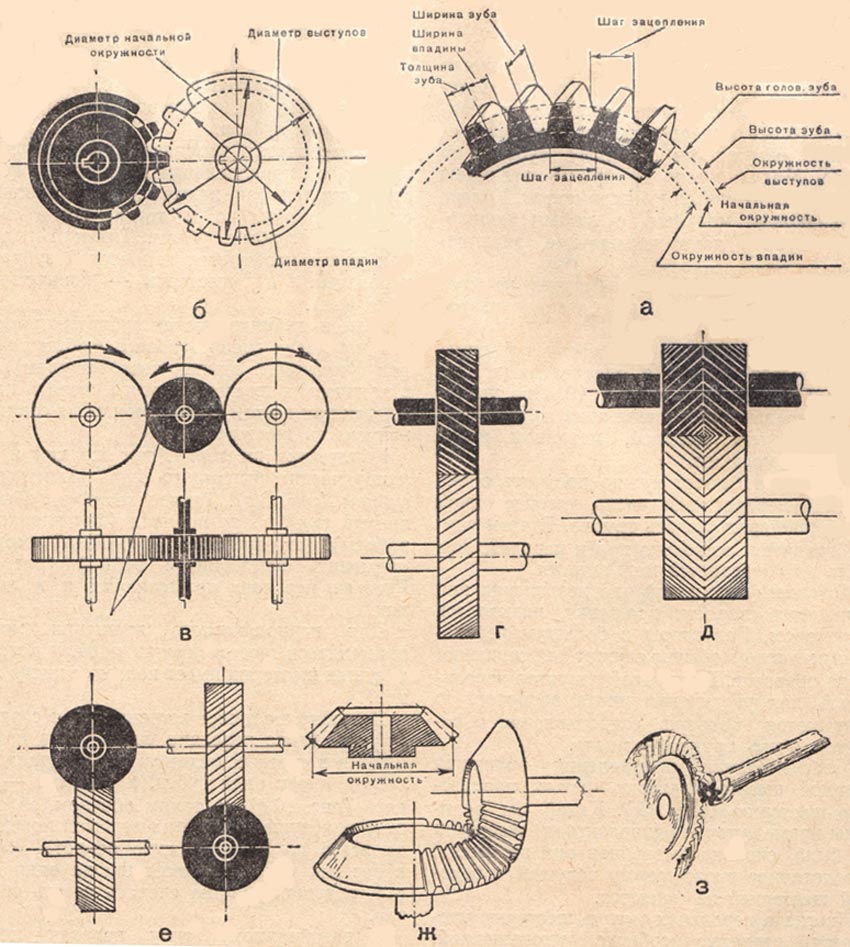
The diameter of the starting circle is the main design diameter of the gears. The distance taken along the initial circle between the axes of adjacent teeth, between the axes of the cavities, or from the beginning of one tooth to the beginning of another, is called the engagement pitch. Of course, the steps of the meshing gears must be equal.
The gear ratio in gears can also be expressed in terms of the number of teeth:
i \u003d z 2 / z 1
Where z2- the number of teeth of the driven wheel, z1- the number of teeth of the drive wheel.
There is another very important value in the gears, which is called the module. The modulus is the ratio of the step to the value? (3.14) or the ratio of the pitch circle diameter to the number of teeth on the wheel. The module, pitch and other gear sizes are measured in millimeters. Wheels with the same module, with any number of teeth, give normal engagement. Gear modules are not taken randomly. Their values are standardized.
The gear ratio of a gear transmission is usually taken within certain limits. It fluctuates up to 1:10. With an increase in the gear ratio, one of the gears becomes very large, the mechanism turns out to be cumbersome. But sometimes it is necessary to get a very large gear ratio, which is difficult to create with one pair of gears. In this case, several pairs are placed and the gear ratio is distributed between them.
Sometimes in gears, a small gear needs to be made especially reduced, for example, in watches, in instruments. In these cases, the gear with the shaft is made from one piece. Such a one-piece gear is commonly called a tribe (tribok).
Often used in cars cylindrical gears, in which the tooth does not go along the axis of rotation, but at a certain angle (r). Such gears run very smoothly at high speeds, and their teeth endure a large load. Wheels with oblique teeth are called helical cylindrical wheels. An even smoother ride with a high strength of the teeth is given by the so-called chevron wheels (d). The teeth of these wheels are beveled in both directions, arranged in a herringbone pattern.
Gear transmission is used not only with parallel shafts when so-called spur gears are used, but also when the shafts run at any angle. Such an angle transmission is called bevel. gear train th, and gears - bevel (g).
bevel gears, as well as cylindrical ones, come with a spiral oblique tooth (z). Such gears are usually used in cars (for smooth operation). In gears, rack and pinion gears can be used. For periodic rotation, a gear pair can be used, in which the drive gear has an incomplete number of teeth.
Rack engagement:
a - a gear with a rack, b - types of rack and pinion gears.
The drive gears are also found with one tooth. Such transmissions were very often used in counting mechanisms. The drive gear has one tooth, and the driven gear has ten, and thus, in one revolution of the drive gear, the driven gear will turn only one tenth of a turn. To turn the driven gear one revolution, the driver must make ten revolutions.
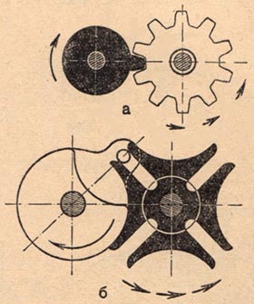
Mechanisms for periodic rotation:
a - a gear with one tooth, b - a Maltese cross.
Gear Advantages:
Significantly smaller dimensions than other gears;
High efficiency (losses in precise, well-lubricated gears 1-2%);
Great durability and reliability.
Gear Disadvantages:
Noise at work;
The need for precision manufacturing.
Gear Application:
The most common type of mechanical transmission. They are used to transmit power - from negligible to tens of thousands of kW.
The so-called Maltese gearing, or the Maltese cross (b) can also be attributed to the disassembled type of gears. The mechanism of the Maltese cross is used for periodic rotation.
Belting
Belt transmission, like gear, is very common. A belt stretched over pulleys covers some part of them. This tight-fitting part (arc) is called the girth angle. The larger the wrap angle, the better the adhesion is formed, the better and more reliable the rotation of the pulleys will be. With a small wrap angle, it may turn out that the belt on the small pulley begins to slip, the rotation will be transmitted poorly or not at all. The angle of wrapping depends on the ratio of the dimensions of the pulleys and their distance from each other. Figures (a, b) show how the wrapping angles change. When it is required to increase the wrap angle, a pressure pulley-roller (c) is placed at the transmission.
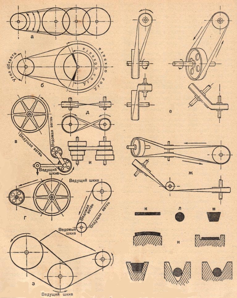
Belting:
a, b - dependence of the wrap angles on the size and location of the pulleys; in - transmission with a tension roller; g - open transfer; d - cross transmission; e - semi-cross gear; g - angular gear; h - twin gear; and - step transmission; to - flat belt; l - round belt; m - trapezoidal belt; n - the location of the belts on the pulleys.
Depending on the location of the shafts and the belt, the belt drive can be of different types.
Open gear (g). Both pulleys with this transmission rotate in the same direction.
Cross transmission (d). Such a transmission is used when it is required to change the rotation of the driven pulley. The pulleys rotate towards each other.
Semi-cross gear (e) is used when the shafts are not parallel, but at an angle.
Angular gear (g) is formed when the shafts go at an angle, but lie, as it were, in the same plane. In this transmission, rollers must be installed to obtain proper belt guidance.
Twin gear (h). With this transmission, belts can go from one drive pulley to several driven pulleys.
In addition to the listed gears, there is also a stepped gear (s). It is used when it is required to change the number of revolutions of the driven shaft. Both pulleys in this gear are made stepped. By rearranging the belt to one or another pair of steps, the number of revolutions of the driven shaft is changed. In this case, the length of the belt remains unchanged.
According to their profile, belts are flat, round and trapezoidal (k, l, m).
The gear ratio of belt drives is taken within 1:4, 1:5, and only in exceptional cases - up to 1:8.
When calculating the belt drive, the sliding of the belt over the pulleys is taken into account. This slippage is expressed in the range of 2-3%. To obtain the desired speed, the diameter of the driven pulley is reduced within the same limits.
Pulleys can be made from plywood or light metals.
Benefits of a belt drive:
Simplicity of design;
The possibility of location of the driving and driven pulleys at large distances (more than 15 meters);
Protection of mechanisms from overload due to the elastic properties of the belt and its ability to slip along the pulleys;
Ability to work with high angular speeds.
Disadvantages of a belt drive:
Gradual stretching of the belts, their fragility (at high speeds it works from 1000 to 5000 hours);
Inconstancy of the gear ratio (due to the inevitable slippage of the belt);
Relatively large sizes.
Belt drive application:
It is used very often, from consumer electronics to industrial mechanisms up to 50 kW.
Worm-gear
The worm gear is used to obtain rotation between shafts that intersect in the same plane. The transmission consists of a screw (worm) and a screw wheel, which are engaged. As the worm rotates, the coils drive the teeth of the wheel and cause it to rotate. Usually the rotation from the worm is transferred to the wheel. Reverse transmission is almost never encountered due to self-braking.
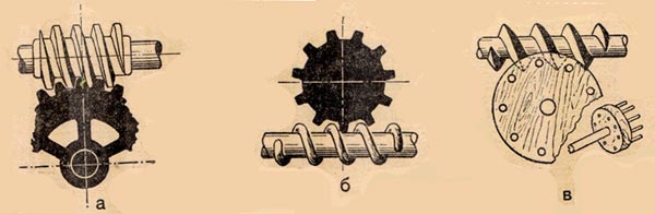
Worm-gear
The worm gear is used most often with large gear ratios ranging from 5 to 300. Due to the large gear ratio, the worm gear is widely used as a mechanism for reducing the speed - a gearbox.
Usually, the worm is connected by means of a clutch to an electric motor, and the worm wheel shaft is connected to machines (machine, winch, conveyor, etc.), to which it transmits the necessary rotation. Structurally worm gear are made into an independent mechanism, placed in a closed case.
Worm gear ratio ( i), depends on the number of worm passes and the number of teeth on the wheel. It can be easily calculated using the formula:
Where Z- the number of teeth of the helical wheel, and K- the number of visits of the worm. Let's solve an example: the motor makes n 1 = 1500 rpm, on the worm gear shaft you need to get n 2 = 50 rpm. The worm is double-threaded, that is K = 2. It is necessary to determine the gear ratio and the number of teeth on the helical gear. The gear ratio is determined from the formula:
i \u003d n 1 / n 2 \u003d 1500/50 \u003d 30
Number of teeth on the gear Z = i*K = 30*2 = 60 teeth.
Reducers can be made in different ways. For some, the worm is made from an ordinary mounting screw, for others it is made by winding onto a rod in the form of a wire spring or a narrow copper strip (on the edge). For strength, the turns to the rod should be soldered. Worm gears are picked up from an unnecessary clockwork. But you can also make them yourself: cut them with a file from a brass or duralumin disc.
In the manufacture of gearboxes, care must be taken to ensure that the screw and gear do not have axial displacement during rotation. In high-speed gearboxes, its shafts should be mounted on bearings.
Advantages of a worm gear:
Smooth and quiet operation;
Large gear ratio.
Disadvantages of worm gear:
Enhanced heat dissipation;
Increased wear;
tendency to seize;
Relatively low efficiency.
Application of worm gear:
Mainly used when a large gear ratio is required.
chain drive
A chain drive, compared to a belt drive, is convenient in that it does not slip and allows you to maintain the correct gear ratio. Chain transmission is carried out only with parallel shafts.
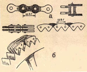
a - lamellar roller chain, b - silent chain.
The main value of the chain transmission is the pitch. The pitch is the distance between the axes of the rollers at the chain or the distance between the teeth of the sprocket.
In addition to roller chains, toothed, so-called silent chains are also widely used in machines. Each link is connected from several toothed plates in a row. The width of this chain is much larger than the roller chain. The asterisk of such a transmission is similar to a gear. Gear chains can operate at high speeds.
The permissible gear ratio of chain drives can be up to 1:15. The smallest number of teeth is taken from sprockets: for roller chains - 9, and for gear chains - 13-15. The distance between the axes of the sprockets is taken not less than one and a half diameter of the large sprocket.
The chain is put on the sprockets not tight, like belts, but with some sagging. A tension roller is used to regulate the tension. The number of revolutions of the driven sprocket depends on the ratio of the teeth on both sprocket.
Advantages of chain transmission:
Less sensitivity to inaccuracies in the location of the shafts;
Possibility of transmission of movement by one chain to several sprockets;
Ability to transmit rotational motion over long distances.
Chain drive disadvantages:
Increased chain noise and wear due to improper design, careless installation and poor maintenance.
Ratchets
In addition to continuous rotational motion, intermittent rotational motion is very often used in machines. This movement is carried out using the so-called ratchet mechanism. The main parts of a ratchet mechanism are: a ratchet (a disc with teeth), a lever and a pawl. Ratchet teeth have a special shape. One side of them is made flat, and the other is sheer or somewhat undercut. The ratchet is fixed on the shaft. The lever, sitting next to the ratchet, can swing freely. There is a pawl on the lever, which lies on the ratchet at one end. With the help of a connecting rod or thrust from one or another driving mechanism, the lever comes into swing. When the lever is deflected to the left, the pawl slides freely along the gentle slope of the teeth without turning the ratchet. When moving to the right, the pawl rests against the ledge of the tooth and turns the ratchet at a certain angle. So, continuously swinging in one direction or another, the lever with the pawl leads the ratchet with the shaft into a periodic rotational motion. For a secure fit of the pawl to the ratchet, the pawl is supplied with a pressure spring.
But more often there is another purpose of the ratchet mechanism - to protect the shaft with the ratchet from turning. So, at the winch, when lifting the load, the ratchet with the dog does not allow the drum to turn back.
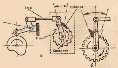
Ratchets:
a - with a one-sided dog; b - with a flip dog.
Sometimes you need to get the rotation of the ratchet not only in one direction, but also in the other. In this case, the teeth of the ratchet are made rectangular, and the dog is crossover (b). Throwing the pawl to the right or left, you can change the rotation of the ratchet.
The number of teeth on the ratchet depends on the desired angle of rotation. On which part of the circle the ratchet turns, so many teeth are made. For example, if 60 ° is one sixth of a circle, then 6 teeth are taken; at 30 ° - one twelfth - 12 teeth are made, etc. Less than six teeth on a ratchet usually does not exist.
The ratchet should be small. A large ratchet will require an increase in lever span and a large crank stroke that pumps the lever. The height of the ratchet tooth should be taken within 0.35-0.4 of the step. The profile of the tooth is made acute-angled, the flat side of the tooth is straight, but it can also be outlined along the radius. It is better to take two levers, placing them on both sides of the ratchet. With two levers, the pawl and the leash from the crank will stand between them and reduce skew during operation. The pawl can be pressed not only with a spring, but also with an elastic band. The end of the pawl should be well beveled so that it rests more securely on the prong.
Converting rotational motion to rectilinear
Crank mechanisms
Crank mechanisms are used to convert rotational motion into reciprocating motion and vice versa. The main parts of the crank mechanism are: the crank shaft, the connecting rod and the slider, hinged to each other (a). The length of the stroke of the slider can be any, it depends on the length of the crank (radius). If we denote the length of the crank by the letter A, and the slider's move through B, then we can write a simple formula: 2A = B, or A = B/2. Using this formula, it is easy to find both the stroke length of the slider and the length of the crank. For example: slider stroke B = 50 mm, it is required to find the length of the crank A. Substituting a numerical value into the formula, we get: A = 50/2 = 25 mm, that is, the length of the crank is 25 mm.
a - the principle of operation of the crank mechanism,
b - one-crankshaft, c - many-crankshaft,
g - a mechanism with an eccentric.
In a crank mechanism, a crankshaft is often used instead of a crankshaft. From this, the essence of the action of the mechanism does not change. The crankshaft can be either with one knee or with several (b, c).
An eccentric mechanism (d) can also be a modification of the crank mechanism. The eccentric mechanism has neither a crank nor knees. Instead, a disk is mounted on the shaft. It is planted not in the center, but displaced, that is, eccentrically, hence the name of this mechanism - eccentric.
In some crank mechanisms, it is necessary to change the stroke length of the slider. At the crankshaft, this is usually done like this. Instead of a solid curved crank, a disk (faceplate) is mounted on the end of the shaft. The spike (leash, on which the connecting rod is put on) is inserted into a slot made along the radius of the faceplate. By moving the spike along the slot, that is, moving it away from the center or bringing it closer, we change the size of the slider stroke.
The course of the slider in the crank mechanisms is uneven. In places of "dead running" it is the slowest.
Crank mechanisms are used in engines, presses, pumps, in many agricultural and other machines.
rocker mechanisms
Reciprocating motion in crank mechanisms can be transmitted without a connecting rod. In the slider, which in this case is called the backstage, a cut is made across the movement of the backstage. The crank pin is inserted into this slot. When the shaft rotates, the crank, moving to the left and right, leads the backstage.
Rocker mechanisms:
a - forced link, b - eccentric with a spring roller, c - rocking link.
Instead of a backstage, a rod enclosed in a guide bush can be used. To fit the eccentric disk, the rod is supplied with a pressure spring. If the rod works vertically, its fit is sometimes carried out by its own weight.
For better movement on the disk, a roller is installed at the end of the rod.
Cam mechanisms
Cam mechanisms are used to convert rotational motion (cam) into reciprocating or other given view movement. The mechanism consists of a cam - a curved disk mounted on a shaft, and a rod, which at one end rests on the curved surface of the disk. The rod is inserted into the guide bushing. For a better fit to the cam, the rod is supplied with a pressure spring. To make the rod slide easily over the cam, a roller is installed at its end.

Cam mechanisms:
a - a flat cam, b - a cam with a groove, c - a drum-type cam, d - a heart-shaped cam, d - a simple cam.
But there are disc cams of a different design. Then the roller slides not along the contour of the disk, but along a curved groove taken out from the side of the disk (b). In this case, no pressure spring is required. The movement of the roller with the rod to the side is carried out by the groove itself.
In addition to the flat cams we have considered (a), drum-type cams (c) can be found. Such cams are a cylinder with a curved groove around the circumference. A roller with a rod is installed in the groove. The cam, rotating, drives the roller in a curved groove and thereby informs the rod desired movement. Cylindrical cams are not only with a groove, but also one-sided - with an end profile. In this case, the roller is pressed against the cam profile by a spring.
In cam mechanisms, instead of a rod, swinging levers (c) are very often used. Such levers allow you to change the length of the stroke and its direction.
The stroke length of a rod or cam lever can be easily calculated. It will be equal to the difference between the small cam radius and the large one. For example, if the large radius is 30 mm, and the small one is 15, then the stroke will be 30-15 = 15 mm. In a mechanism with a cylindrical cam, the stroke length is equal to the amount of displacement of the groove along the axis of the cylinder.
Due to the fact that cam mechanisms make it possible to obtain a variety of movements, they are often used in many machines. Uniform reciprocating motion in machines is achieved by one of the characteristic cams, which is called heart-shaped. With the help of such a cam, the shuttle coil is evenly wound at the sewing machine.
Toggle mechanisms
Often in machines it is required to change the direction of movement of any part. Suppose the movement is horizontal, and it must be directed vertically, to the right, to the left, or at some angle. In addition, sometimes the stroke length of the operating lever needs to be increased or decreased. In all these cases, hinged-lever mechanisms are used.

Levers and their application in articulated-lever mechanisms.
The figure shows a toggle mechanism associated with other mechanisms. The lever mechanism receives a rocking motion from the crank and transmits it to the slider. The stroke length with a hinged-lever mechanism can be increased by changing the length of the lever arm. The longer the arm, the greater will be its swing, and hence the feed of the part associated with it, and vice versa, the smaller the arm, the shorter the stroke.
© "Encyclopedia of Technologies and Methods" Patlakh V.V. 1993-2007
Transfer - This is a device designed to transmit movement over a distance and to convert movement parameters.
There are three main types of gears - mechanical, hydraulic and pneumatic.
it is a transmission in which motion is transmitted by means of rigid bodies.
mechanical transmission- a mechanism that serves to transfer and convert mechanical energy from a power machine to an actuator (organ) of one or more, as a rule, with a change in the nature of movement (changes in direction, forces, moments and speeds). As a rule, rotational motion transmission is used. The drive of working bodies, chassis and other components of machines is carried out with the help of power transmissions, which not only transmit movement, but also change the speed, and sometimes the nature and direction of movement.
Transfers are:
Mechanical;
hydraulic;
Electrical;
Mixed.
In each transmission, the element that transmits power is called the master, and the element to which this power is transmitted is called the slave.
Transmissions are mainly used lowering.
The transmission is characterized by: input, output and internal parameters:
- speed: linear; angular.
- force factors: effort (in translational motion); torques (during rotational motion).
Power: gear ratio; efficiency.
According to their design, mechanical transmissions are distinguished:
Friction gears- friction transmission with direct contact of rolling elements, mainly used in auxiliary mechanisms. Advantages: simple, smooth, silent operation. Flaws: special clamping devices are needed, wear, increased load.
Belt drives - flexible connection mainly used in auxiliary mechanisms. Advantages: simplicity of design and shock-free operation, the ability to use with significant distances between the shafts, silent. Flaws: slippage, large dimensions, low durability, stretching.
gears - gearing with direct contact, the most widespread. Dignity: small gabaites; high efficiency; great durability and reliability; possibility of application in a wide range. Flaws: noise at work; transfer of large axial forces to the shafts; complex manufacturing technology.
Worm gears– gearing with direct contact. Advantages: noiseless and smooth operation; high movement accuracy; providing the possibility of self-braking. Flaws: low efficiency; small transmitted power; increased wear.
Chain destined to transfer motion between two parallel shafts with a sufficiently large distance between them. Advantages: the ability to transmit traffic over long distances; smaller than that of belt drives, dimensions; lack of slip; sufficiently high efficiency, the possibility of easy replacement of the chain. Flaws: relatively rapid wear of hinges operating in conditions of abrasive ingress; requires more difficult maintenance - lubrication, adjustment in comparison with V-belt drives; significant vibrations and noise at sufficiently high speeds and low accuracy of structural elements.
Devices designed to transmit engine power by the executive bodies of machines are called transmission mechanisms or mechanical transmissions.
Mechanical transmissions allow you to lower (increase) the speed, carry out stepwise or stepless regulation of it in a wide range, change the direction of movement, convert one type of movement into another, set several mechanisms in motion from one engine.
Types of mechanical gears LEGO "Technic":
v gear (cylindrical, conical, worm, rack, planetary);
v with flexible elements(chain, belt);
v friction.
According to the method of transmission of movement:
v movement from shaft to shaft is transmitted due to friction forces (belt, worm, friction);
v movement is transmitted by gearing (toothed, chain, toothed belts, worm).
Consider the principle of operation of a mechanical transmission. We will conditionally call a pair that performs rotational movement wheels. The wheel from which the rotation is transmitted is called the driving wheel, and the wheel receiving the movement is called the driven wheel.
Knowing the RPM of the drive wheel, we can determine the RPM of the driven wheel.
The number of revolutions of the driven wheel depends on the ratio of the diameters of the connected wheels. If the diameters of both wheels are the same, then the wheels will spin at the same speed. If the diameter of the driven wheel is larger than the driving wheel, then the driven wheel will spin more slowly, and vice versa, if its diameter is smaller, it will make more revolutions (Fig. 211).
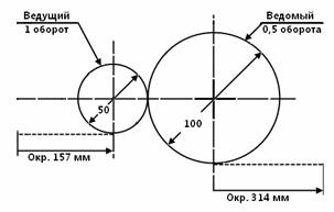
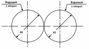
Rice. 211 Dependence of the number of revolutions on the diameters of the wheels
LEGO Technic uses electric motors to power the models. main reason of this is that the electric motor is compact, constantly ready to work and convert electrical energy to a mechanical one as long as voltage is applied to it (more on the various LEGO Technic electric motors will be discussed in § 26).
Each engine has its own mechanical power ( N) specific to a specific engine type. It is important that the mechanical power of the engine depends on two quantities: angular velocity and torque.
Angular velocity (ω ) is the number of revolutions of the motor shaft produced during a given time interval. In Lego mechanisms, the angular velocity of the rotating axes of the engine is converted into the linear velocity of the vehicle. The units of angular velocity are revolutions per minute (revolutions per second). Various types engines lego have various meanings angular speeds, from less than 20 rpm to over 1000 rpm.
Torque (M) is the force with which the drive shaft rotates. The higher the torque, the harder it is to stop the drive shaft. Therefore, motors that offer high torque are generally preferred as they can drive heavy vehicles or more complex machinery than low torque motors (the more torque, the more more powerful engine). The unit of measurement for torque in LEGO motors is Ncm (Newton product per centimeter). The torque value for LEGO Technic motors ranges from 0.5 to 16.7 Ncm.
Mechanical power in some simplification is the product of torque and angular velocity.
mechanical power = torque × angular velocity
N= Mω
Engine power at normal speed rotation is a constant value, therefore M= N/ ω , i.e. The motor torque is inversely proportional to the angular velocity of the motor shaft.
IN practical calculations the relationship between power, shaft rotation speed and torque on the shaft is determined for electric motors by the formula: М=5.8N/n, M- torque on the shaft, N- power, n- speed of rotation of the shaft.
Thus, in order to increase the torque with the same engine power that we have, it is necessary to reduce the speed of rotation of the shaft. This can be done using special mechanisms called gearboxes(from English word reduce - reduce, lower).
Mechanisms designed to increase the speed, and, consequently, to reduce the torque on the shaft, are called multipliers(multiplication - multiplication, increase).
Consider a model of a wheeled robot - we want it to be light and fast. Since a light robot does not need much torque to move, we can convert the speed of the motor shaft by using a pair of gears. Using the above rule, we need to put a larger diameter gear (drive gear) on the motor shaft, and use a smaller diameter gear as the driven gear, while we will reduce the torque and increase the speed.
Question: how to change the torque and speed if a gear of a smaller diameter is used as the drive wheel than the driven gear?
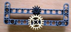
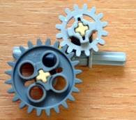
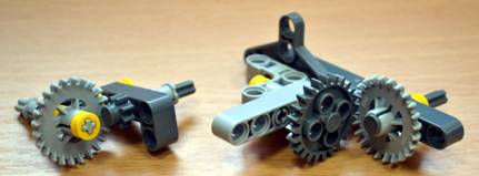
gears
A gear is a mechanism that serves to transmit rotational motion from one shaft to another and change the speed of rotation through gears and racks.


Rice. 212 Gears
The number of teeth on gear wheels can be different. The smallest number of teeth is six. Gears with this number of teeth were called gears. Later, the name came to be applied to all gears with any number of teeth.

Rice. 213 Examples of mounting gears with beams

So, the gear train can:
v transmit rotational motion;
v change the rpm;
v increase or decrease the force of rotation;
v change direction of rotation.
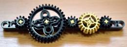
Depending on the shape of the wheels and their relative position distinguish the following types of gears : cylindrical, conical, worm, rack, planetary.
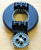
Cylindrical gear consists of two or more cylindrical wheels mounted on parallel shafts.
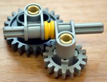
Rice. 215 Cylindrical gear
Bevel gear consists of two conical wheels located on two shafts, the axes of which intersect. The angle of intersection can be any, but usually it is 90º.
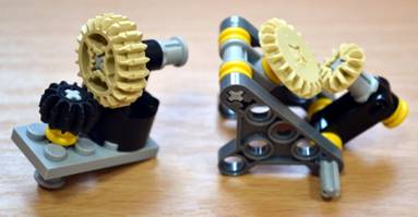
Rice. 216 Bevel gear
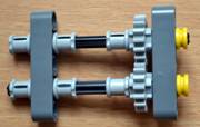
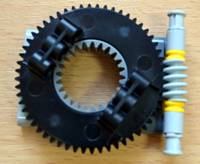
Worm gear (gear screw gear) - mechanical transmission, carried out by engaging the worm and the worm wheel associated with it. Worm gear is used for crossing but not intersecting shafts. The worm gear consists of a screw (worm) and a gear.
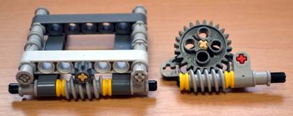
Rice. 217 Worm gear
The worm gear has a number of unique properties. Firstly, it can only be used as a driving gear, and cannot be used as a driven gear. This is very convenient for mechanisms that are needed to lift and hold a load without loading the engine. There are many possible applications this property of the worm gear, for example, in many types of cranes and loaders, railway barriers, drawbridges, winches. The LEGO worm gear is very widely used in the design of the grip for the robotic arm.
Secondly, characteristic feature worm gear is that it has a large gear ratio. That's why worm gears used as a buck whenever there is very high torque.
Conclusion: Worm gear has a number of advantages:
v Takes up little space.
v Has the property of self-braking.
v Reduces rpm by many times.
v Increases drive force.
v Changes the direction of rotation by 90°.
rack and pinion - a mechanical transmission that converts the rotational movement of the gear into the translational movement of the rack and vice versa. The rack can be considered as a circle of a large gear wheel elongated in a straight line.
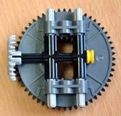
It should be noted that there are ring gears and internal gears in LEGO sets.
ring gear - This special type gears, their teeth are on the side surface. Such a gear works, as a rule, in tandem with a spur gear.
Rice. 220 Connections crown gear and spur gears with 8 and 24 teeth
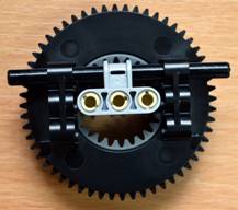
Gears with internal gearing have teeth cut with inside. When they are used, one-way rotation of the driving and driven gears occurs. This gear train has less friction costs, which means higher efficiency*. Gears with internal gearing are used in mechanisms of limited dimensions, in planetary gears, in the drive of a manipulator robot.
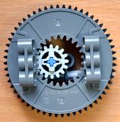

Rice. 221 Internal gear
The LEGO internal gear has teeth on the outside so it can be used in gears like a 56 tooth spur gear.


Rice. 222 Ways of connecting a wheel with internal gearing to a cylindrical gear, a wheel with a crown and a "worm"
Rice. 223 Method of connecting a wheel with internal gearing to a motor
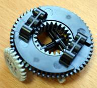
planetary gear
planetary gear (differential gear) - a mechanical system consisting of several planetary gear wheels(gears) rotating around the central, sun, gear. Usually planetary gears are fixed together with a planet carrier. The planetary gear may also include an additional external annular (crown) gear having internal engagement with the planetary gears.
This transmission has found wide application, for example, it is used in kitchen appliances or automatic transmission of a car.
The main elements of the planetary gear can be considered as follows:
v Sun gear: located in the center;
v Carrier: rigidly fixes the axes of several planetary gears (satellites) of the same size relative to each other, which are engaged with the sun gear;
v Ring gear: external gear having internal engagement with planetary gears.

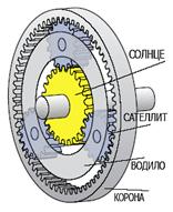
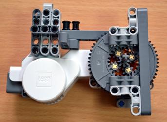
Rice. 224 An example of a planetary gear: the carrier is motionless, the sun is leading, the crown is driven
In a planetary gear, torque is transmitted using any (depending on the selected gear) of its two elements, of which one is the master, the second is the slave. The third element is stationary (table 8).
Table 8. Elements of the planetary gear
|
Fixed |
Leading |
Slave |
Broadcast |
|
Crown |
lowering |
||
|
Boosting |
|||
|
Sun |
lowering |
||
|
Boosting |
|||
|
carrier |
Reverse, lowering |
||
|
Reverse boost |
Reverse - change the course of the mechanism to reverse, opposite.

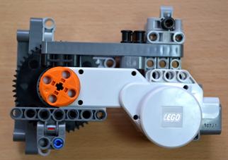
Rice. 225 An example of the design of a planetary gear: the crown is stationary, the carrier is leading, the sun is driven
Mechanical transmissions with flexible elements
To transfer motion between shafts relatively far apart, mechanisms are used in which the force from the driving link to the driven one is transmitted using flexible links. Belts, cords, chains of various designs are used as flexible links.
Gears with flexible links can provide a constant and variable gear ratio with a step or smooth change in its value.
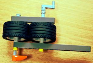
Belting
The belt drive consists of two pulleys mounted on shafts and a belt covering these pulleys. The load is transmitted due to the friction forces that arise between the pulleys and the belt due to the tension of the latter. The belt drive is not very sensitive to the relative position of the drive and driven shafts. They can even be turned at right angles to each other or put on a belt in the form of a crossed loop, and then the direction of rotation of the driven shaft will change.
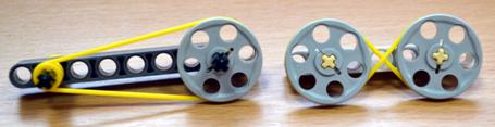

Rice. 226 Belt drive
chain drive
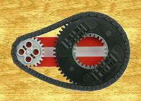
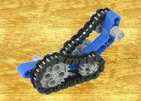
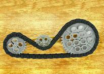
Rice. 227 Chain drive
friction gear
Rice. 228 Friction gear
With frictional transmission, the rotation from one wheel to another is transmitted using friction force. Both wheels are pressed against each other with some force and due to the friction that occurs between them, one rotates the other.
Friction gears are widely used in cars. Disadvantage of friction gear: a large force pressing on the wheels, causing additional friction in the car, and therefore requiring additional force to rotate.
In addition, the wheels during rotation, no matter how they are pressed against each other, give slippage. Therefore, where an exact ratio of the number of revolutions of the wheels is required, the friction transmission does not justify itself.
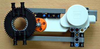
Project "Automatic barrier":
1. Design a model of an automatic barrier.
Specifications:
b) the design uses a worm gear;
c) automatic raising and lowering of the barrier boom must be carried out using an ultrasonic sensor.
4. As part of the robotics circle, make an automatic barrier.
6. In workbook write a description of the automatic barrier.
Project "Turnplatform":
1. Design a turntable model.
Specifications:
a) the model includes one servomotor, NXT microcontroller;
b) the design uses a gear with internal gearing;
c) automatic rotation of the platform occurs with the help of a touch sensor (light sensor).
2. Sketch the model in the workbook.
3. Discuss the project with the teacher.
4. As part of the robotics circle, make a turntable.
5. Using the NXT-G programming language, write a program to control the model.
6. Write a description of the turntable in your workbook.
Project "Slidingautomatic doors":
1. Design a model of automatic sliding doors.
Specifications:
a) the model includes one servomotor, NXT microcontroller;
b) rack and pinion is used in the design;
c) automatic door opening occurs with the help of an ultrasonic sensor (light sensor).
2. Sketch the model in the workbook.
3. Discuss the project with the teacher.
4. As part of the robotics circle, make a model of automatic sliding doors.
5. Using the NXT-G programming language, write a program to control the model.
6. Write a description of the automatic sliding door model in your workbook.